Chromatography columns and their operation

a technology of chromatography and columns, applied in the direction of solid sorbent liquid separation, component separation, water/sludge/sewage treatment, etc., can solve the problems of difficult access to the upper mesh, difficult manoeuvre without a powered lift, and significant obstructions around, etc., to achieve the effect of exceeding the safe reach of the structur

Active Publication Date: 2009-10-20
SARTORIUS STEDIM CHROMATOGRAPHY SYST LTD
View PDF21 Cites 21 Cited by
  • Summary
  • Abstract
  • Description
  • Claims
  • Application Information

AI Technical Summary

Benefits of technology

[0026]Compared with existing methods, this has the radical advantage that the access positions for the first and second end structures can be relatively close to one another. In the preferred orientation, where the first end and second end are the top and bottom respectively, the first end structure appears below the column, greatly reducing the potential access height requirement. Separation of the second end structure from the column—necessary for access to the second end structure—is also involved in access to the first end structure, potentially simplifying the procedure e.g. compared with that described above with reference to FIGS. 1 to 5 in which the column tube had to be lowered onto the base to expose the top piston, inevitably covering the bottom end cell. In the present procedure, both may be accessible at the same stage.
[0033]By operating the drive from one end, in practice preferably the base of the column which may be a base mounted on a stand, we can provide the advantages of the invention without relying on overhead structures or separate units. Nevertheless, the skilled person will appreciate that the advantageous exposure of the piston at the opposite end of the column tube may be achieved by other means if extra drives or attachments to other structures are tolerated, e.g. to drive the piston down from a fixed structure above, and / or to lift the column tube up or down relative to its base e.g. by a similar means, or to support the tube and drive the base downwardly. In general, use of dedicated drives for the different functions simplifies the drive connections but makes the apparatus more bulky, complicated and expensive overall, to the extent that it may be difficult to mount the various drives while retaining adequate access to the column area.

Problems solved by technology

The alignment and lifting structures cause significant obstructions around the tube, and need to be carefully laid out to provide sufficient clearance at some part of the circumference for insertion / removal of the permeable retaining elements if this is to be an operational requirement.
The illustrated column has a 1400 mm diameter and would be very difficult to manoeuvre without a powered lift.
The described apparatus and procedure have however the drawback that access to the upper mesh is difficult; it has to be removed at quite a distance above the ground.
For such a large and delicate component this is a significant issue.
This gives lower access in the final position, but the swinging over of the piston would be a risky matter with a large column, so that this proposal is limited to smaller columns.

Method used


Image

  • Chromatography columns and their operation
  • Chromatography columns and their operation
  • Chromatography columns and their operation

Examples


Embodiment Construction

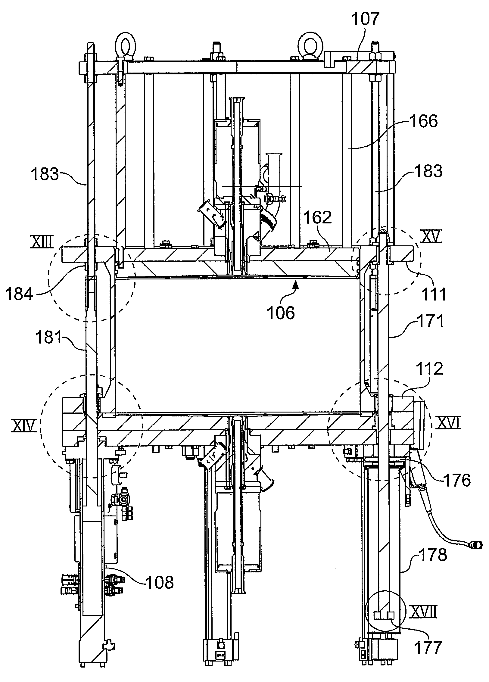
[0059]The column components are broadly similar to those in FIGS. 1 to 5 discussed previously. Thus, the cylindrical stainless steel column tube 101 has upper and lower integral flanges 111, 112, and the base 105 consists of a steel backing plate 152 and a contoured cell plate 153 which carries the bed support mesh. Releasable threaded studs 157 hold the bottom column flange 112 down onto the base, clamping a fixed seal 159 described later. The column base 105 stands on support legs 151, here a wheeled mobile support, providing a component space beneath the base.

[0060]Continuing with reference to FIGS. 6 to 9, three hydraulic drive cylinders 108 are mounted to the underside of the base plate 152, and each operates a drive rod 181 extending up slidably through an opening in the base 105, a corresponding opening in the lower tube flange 112 and up to the upper flange 111. The upper flange 111 has corresponding holes, and a drive extension rod 183 has its bottom end passing through thi...


PUM

PropertyMeasurementUnit
diameteraaaaaaaaaa
diameteraaaaaaaaaa
internal diameteraaaaaaaaaa

Abstract

A method of operating chromatography column apparatus comprising a column tube (101) and first and second discrete end cell structures, associated with the respective ends of the column tube and positionable to close off the column tube and define therein a column space for retaining chromatography medium in use of the apparatus. The first end cell portion comprises a piston portion (106) fitting slidably in the column tube. The column tube and the second end cell structure are separated to provide an access spacing between them. The piston portion (106) of the first end cell structure is advanced through the column tube to expose it at the open second end of the column tube, for maintenance of the piston portion thus exposed. Corresponding chromatography apparatus is another aspect of the disclosure.

Description

REFERENCE TO RELATED APPLICATIONS[0001]This application is a 371 of PCT / GB04 / 05184 filed Dec. 10, 2004FIELD OF THE INVENTION[0002]This invention has to do with chromatography apparatus and methods. It is particularly concerned with systems and methods for gaining access to components of the column e.g. for maintenance, notably the column end cell structures.BACKGROUND OF THE INVENTION[0003]The present discussion relates to apparatus and methods useful in industrial-scale chromatography, e.g. large-scale preparative purification of fine chemicals and pharmaceuticals, including biological products. It is not concerned with laboratory-scale apparatus. Conventionally an industrial-scale chromatography column has a cylindrical axially-vertical column tube with top and bottom end cells, each of which provides a strong backing plate with a fluid inlet / outlet and support for a layer of mesh, sinter or other fluid-permeable retaining material which lets process liquid flow into and out of th...

Claims


Application Information

Patent Timeline
Patent Type & Authority Patents(United States)
IPC IPC(8): B01D15/08B01D15/22G01N30/52G01N30/60
CPCG01N30/6021G01N30/603B01D15/22G01N30/6047G01N2030/522
Inventor SPENCER, GERALD JAMESWALKER, NEIL JOHNSCOTT, JOHN MACKAY
Owner SARTORIUS STEDIM CHROMATOGRAPHY SYST LTD
Why Eureka
Try Eureka