
Distributed micro instruction set processor architecture for high-efficiency signal processing

a micro instruction set and processor technology, applied in the direction of multi-programming arrangements, instruments, program control, etc., can solve the problems of large computational resources required regardless, several computationally expensive functions of communication protocols used in wireless communication systems, and inability to achieve significant computational resources, etc., to achieve efficient process switching and flexible computational support

Active Publication Date: 2009-10-20
INTEL CORP +1
View PDF13 Cites 0 Cited by
  • Summary
  • Abstract
  • Description
  • Claims
  • Application Information

AI Technical Summary

Benefits of technology

This patent is about wireless communication systems that use special processors to support different tasks in the system. The technical effect of this invention is to improve the efficiency and performance of wireless communication systems by allowing them to handle more complex tasks without overwhelming the system.

Problems solved by technology

Communication protocols used in wireless communication systems include several computationally expensive functions.
Therefore, significant computational resources are required regardless of which communication protocol is used in a wireless communication system.
These computationally expensive functions include timing adjustment estimating for delay lock loop and channel estimation processing as well as frequency error estimation, finger energy estimation, and signal-to-interference (SIR) estimation.
At any given instance, a communication protocol requires that several computationally expensive functions be performed to effectively track each echo associated with each mobile hosted by the wireless communication system.
While prior art DSPs are functional and have considerable computational ability, they are somewhat unsatisfactory.
In particular, prior art DSPs take an unsatisfactory amount of time to switch from one process to another process.
Typically, in order to perform a process switch in prior art systems, an expensive hardware interrupt is generated.
Because this prior art process switch takes a considerable number of chip cycles, it is unsatisfactorily slow.
The use of large numbers of conventional DSPs, which are not optimized for a given application, drive up the cost of making such base stations and it reduces their energy efficiency.
Thus, prior art base stations have an unsatisfactory energy consumption profile.
Another problem with known communication architectures arises when support for high channel densities, or related computationally expensive tasks, is required.
However, the addition of DSPs in known architectures increases the amount of overhead to each DSP.
Thus, known architectures have a nonlinear problem, in which the incremental addition of a DSP, in order to increase computational resources, does not provide a linear incremental increase in the amount of overhead on each DSP.
The failure to achieve a linear relationship between the number of DSPs in an architecture and the processing power of the architecture arises because each DSP must coordinate with every other DSP in the architecture.
Taken to theoretical limits, the incremental addition of DSPs will provide very little additional computational improvement in known architectures.
Thus, known architectures are not optimal because of the high degree of overhead that is incurred when multiple DSPs are used.
Yet another problem with known architectures is that the signal datapath is only loosely coupled in the architecture through an inefficient interrupt mechanism.
Thus, each component within the datapath of prior art architectures needs to coordinate with other components in the datapath using inefficient interrupts.
The use of such interrupts is yet another source of inefficiency in known architectures.

Method used


Image

  • Distributed micro instruction set processor architecture for high-efficiency signal processing
  • Distributed micro instruction set processor architecture for high-efficiency signal processing
  • Distributed micro instruction set processor architecture for high-efficiency signal processing

Examples


Embodiment Construction

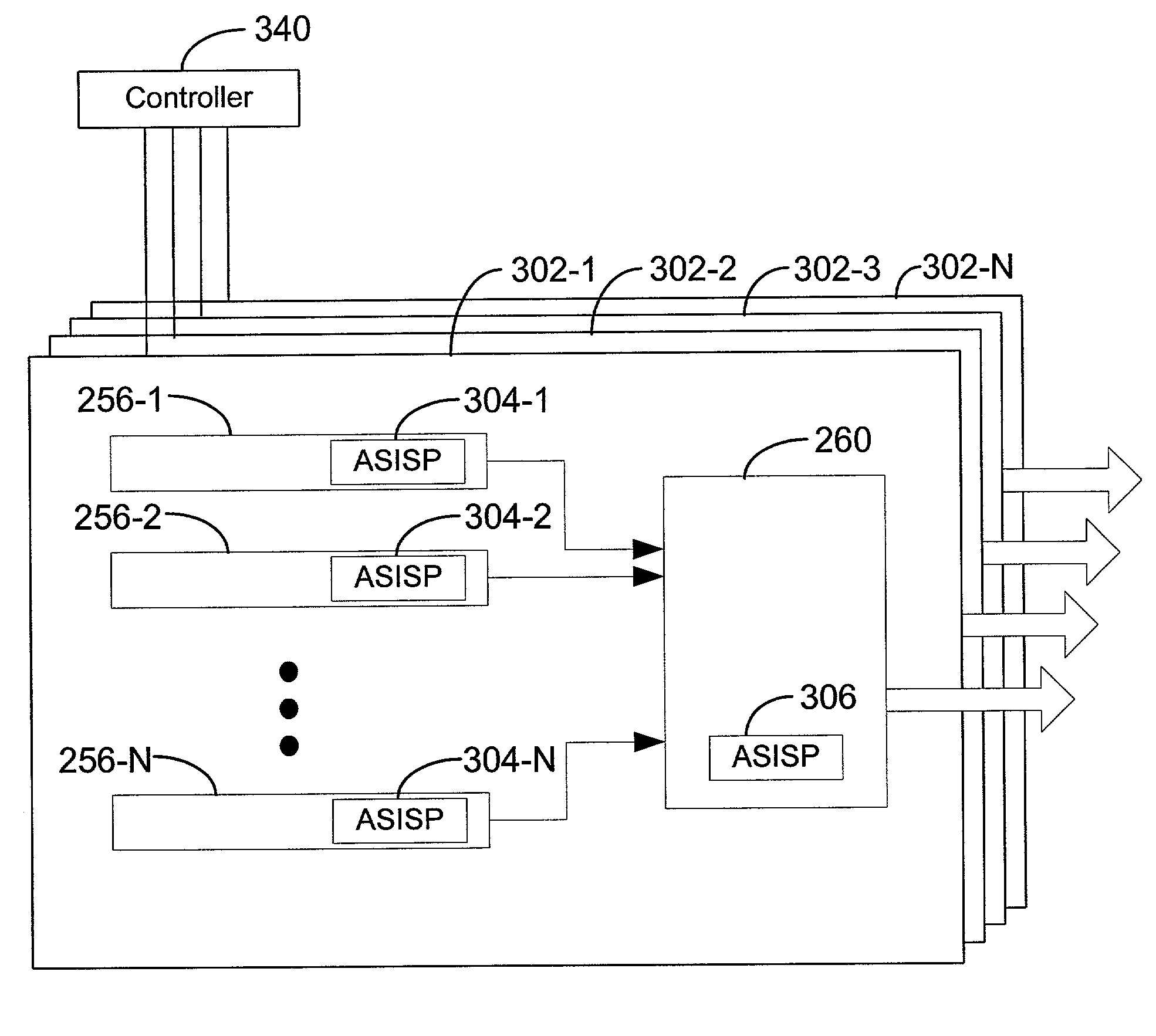
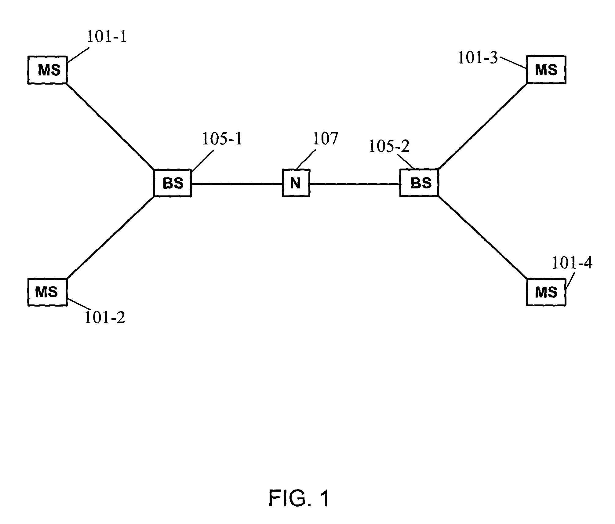
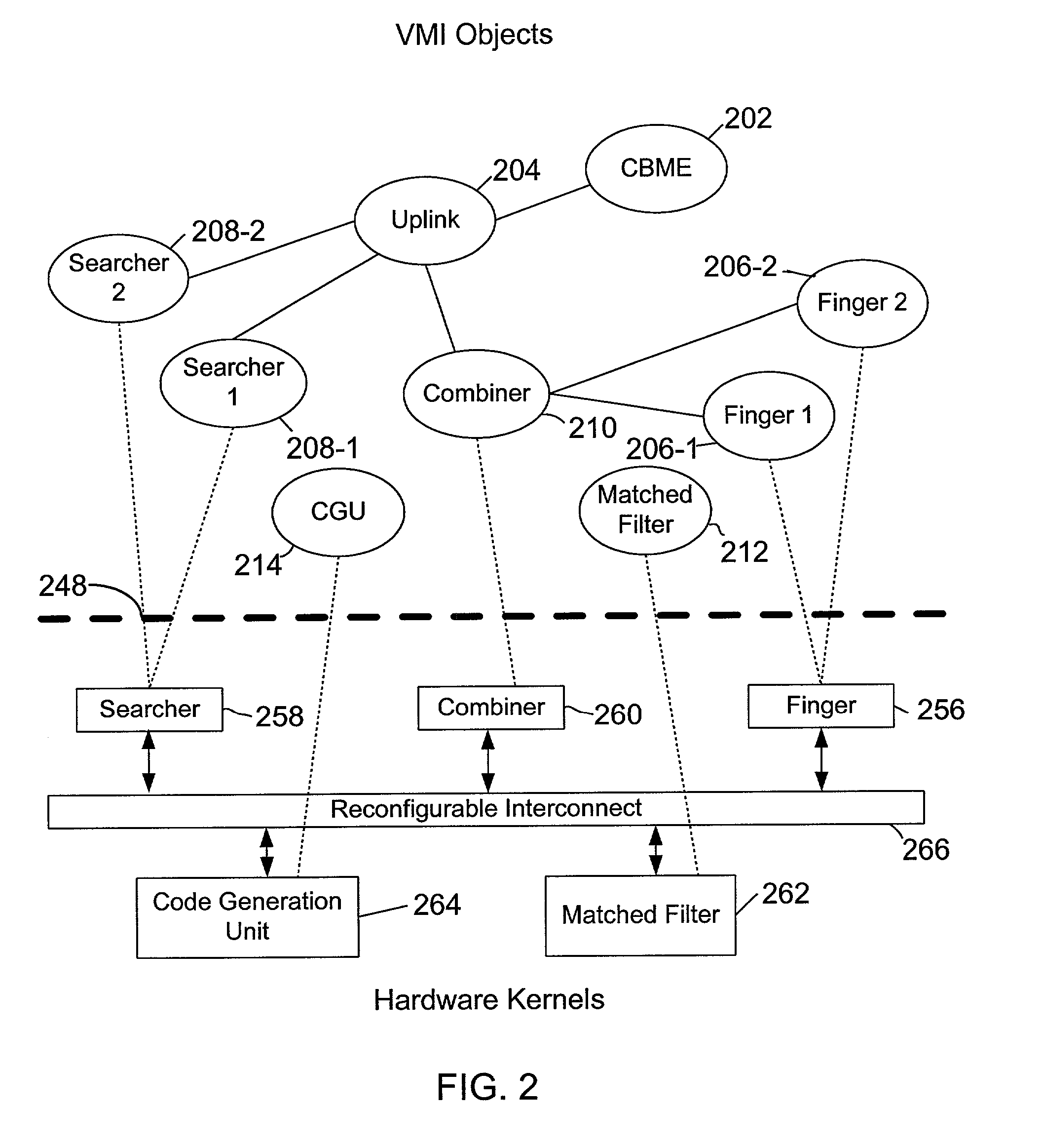
[0042]Reference will now be made in detail to the preferred embodiments of the invention, examples of which are illustrated in the accompanying drawings. While the invention will be described in conjunction with preferred embodiments, it is understood that the description is not intended to limit the invention to these embodiments. Rather, the invention is intended to cover alternatives, modifications and equivalents, which may be included within the spirit and scope of the invention, as defined by the appended claims. Additionally, in the following detailed description of the present invention, numerous specific details are set forth in order to provide a thorough understanding of the present invention. However, it will be apparent to one of ordinary skill in the art that the present invention may be practiced without these specific details. In other instances, well-known methods, procedures, components, and circuits have not been described in detail so as not to obscure important ...


PUM


Abstract

A wireless communication system hosts a plurality of processes in accordance with a communication protocol. The system includes application specific instruction set processors (ASISPs) that provided computation support for the process. Each ASISP is capable of executing a subset of the functions of a communication protocol. A scheduler is used to schedule the ASISPs in a time-sliced algorithm so that each ASISP supports several processes. In this architecture, the ASISP actively performs computations for one of the supported processes (active process) at any given time. The state information of each process supported by a particular ASISP is stored in a memory bank that is uniquely associated with the ASISP. When a scheduler instructs an ASISP to change which process is the active process, the state information for the inactivated process is stored in the memory bank and the state information for the newly activated process is retrieved from the memory bank.

Description

[0001]This application claims priority to the U.S. Provisional Patent Application DISTRIBUTED MICRO INSTRUCTION SET PROCESSOR ARCHITECTURE FOR HIGH-EFFICIENCY SIGNAL PROCESSING, Ser. No. 60 / 220,295, that was filed Jul. 24, 2000.CROSS-REFERENCE TO RELATED APPLICATIONS[0002]Related applications incorporated herein by reference are as follows:[0003]A CONFIGURABLE CODE GENERATOR SYSTEM FOR SPREAD SPECTRUM APPLICATIONS, U.S. patent application No. 09 / 751,782, filed Dec. 29, 2000.[0004]APPARATUS AND METHOD FOR CALCULATING AND IMPLEMENTING A FIBRONACCI MASK FOR A CODE GENERATOR, U.S. patent application No. 09 / 751,776, filed Dec. 29, 2000.[0005]A FAST INITIAL ACQUISITION AND SEARCH DEVICE FOR A SPREAD SPECTRUM COMMUNICATION SYSTEM, U.S. patent application No. 09 / 751,777, filed Dec. 29, 2000.[0006]A CONFIGURABLE ALL-DIGITAL COHERENT DEMODULATOR SYSTEM FOR SPREAD SPECTRUM APPLICATIONS, U.S. patent application No. 09 / 751,783, filed Dec. 29, 2000.[0007]A CONFIGURABLE MULTIMODE DESPREADER FOR SP...

Claims


Application Information

Patent Timeline
Patent Type & Authority Patents(United States)
IPC IPC(8): H04W72/00G06F9/30G06F9/46G06F9/48
CPCG06F9/30079G06F9/30083G06F9/30087G06F9/3009G06F9/462G06F9/4881G06F15/78G06F9/3885Y02B60/144Y02D10/00
Inventor CHEN, SONGCHOU, PAUL L.WOODTHORPE, CHRISTOPHER C.BALASUBRAMONIAN, VENUGOPALRIEKEN, KEITH
Owner INTEL CORP
Learn More