
Device and method of controlling hydraulic drive of construction machinery

a technology of hydraulic drive and control device, which is applied in the direction of electrical control, positive displacement liquid engine, fluid coupling, etc., can solve the problems of decreasing operability, achieve stable stable operation speed or drive torque of work machine, and achieve stable operation speed or drive torque

Active Publication Date: 2009-10-27
KOMATSU LTD
View PDF9 Cites 9 Cited by
  • Summary
  • Abstract
  • Description
  • Claims
  • Application Information

AI Technical Summary

Benefits of technology

The present invention relates to a hydraulic control system for construction machines that use a single engine to drive both the work machine and the auxiliary machine. The system includes an operation state detector and a controller that receives a signal from the detector and controls the engine and the hydraulic pump for the work machine. The controller identifies the operation mode and controls the engine and pump torque to achieve a desired operation speed or drive torque. This results in stable operation of the work machine and reduces the impact on the operator's intentions. The system also includes a mode for controlling the engine output torque and absorption torque of the pump to achieve a constant revolution speed or torque. The controller determines the engine output torque control line and pump torque control line so that the engine revolution speed or output torque matches the desired operation mode. This ensures stable operation of the work machine and reduces the impact of changes in the load on the operation speed.

Problems solved by technology

The resultant problem is that the operation rate or drive torque (for example, an excavation force) of the work machine changes, regardless of the operator's intentions, during the work in the same work mode, thereby decreasing operability.

Method used


Image

  • Device and method of controlling hydraulic drive of construction machinery
  • Device and method of controlling hydraulic drive of construction machinery
  • Device and method of controlling hydraulic drive of construction machinery

Examples


Embodiment Construction

[0024]An embodiment of the device for controlling hydraulic drive in accordance with the present invention will be described below with reference to the appended drawings.

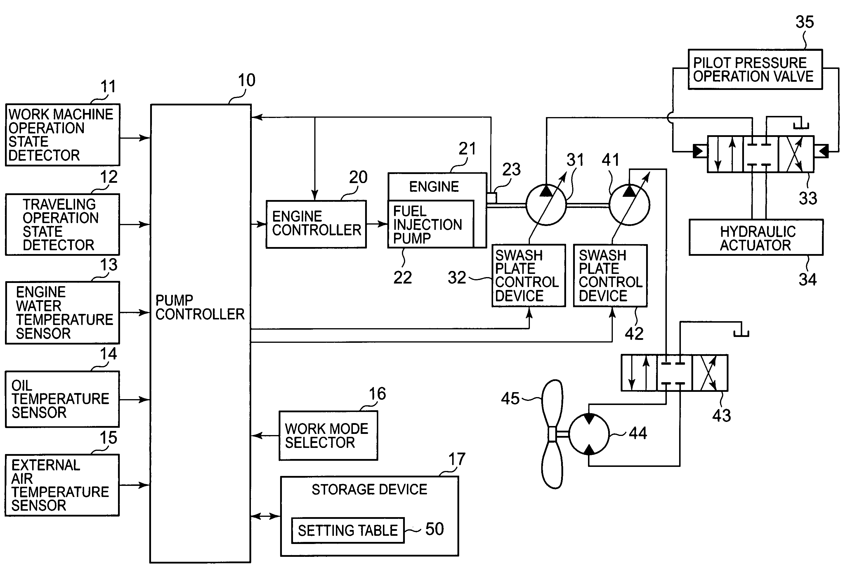
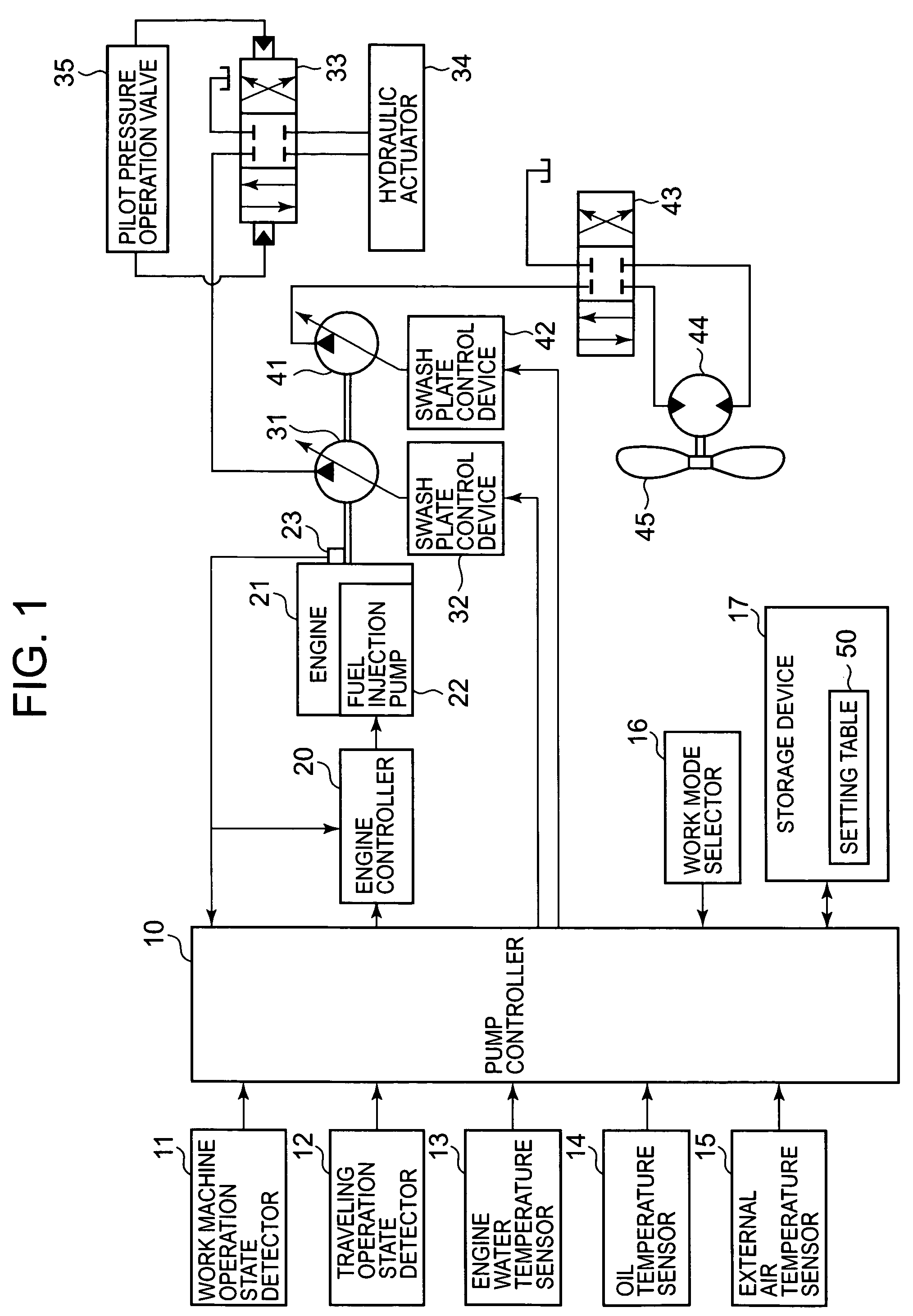
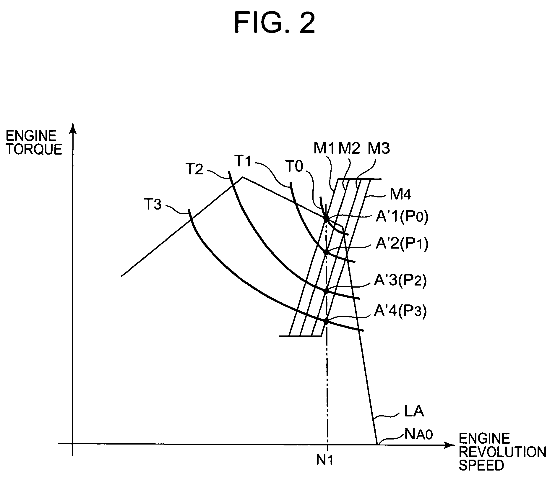
[0025]FIG. 1 is a block diagram illustrating the hardware structure of an embodiment of the hydraulic control device in accordance with the present invention. FIG. 2 is an explanatory drawing of engine output characteristic and a pump absorption torque characteristic that illustrate the operation of the hydraulic control device. First, the hardware structure will be explained with reference to FIG. 1 and FIG. 2. Here, the explanation will be conducted with reference to a hydraulic shovel as an example of a construction machine using the present invention.

[0026]As shown in FIG. 1, a hydraulic pump 31 for a work machine and a hydraulic pump 41 for an auxiliary device are linked via a power take-off device (not shown in the figure) to an output shaft of an engine 21. The oil discharged under pressure from the hydrauli...


PUM


Abstract

In construction machinery, control is conducted to keep a work machine to operate at a constant speed regardless of the operation thereof. Different engine output lines T0-T3 and pump torque lines M1-M4 are defined for different operation types. All the matching points of the engine output lines T0-T3 and pump torque lines M1-M4 designate a constant engine speed N1. One engine output line and one pump torque line are selected according to the operation type presently selected. An output horsepower of the engine is controlled on an equal horsepower line corresponding to a sum of a horsepower for an auxiliary machine and a horsepower at a matching point of the selected lines. The pump torque for the work machine is controlled on the selected pump torque line. The engine operates at a constant speed N1 even when the operation type varies or the horsepower for the auxiliary machine changes.

Description

RELATED APPLICATION[0001]This application is a National Stage of International Application No. PCT / JP2004 / 018313 filed on Dec. 8, 2004, which claims priority to JP 2003-410518, filed on Dec. 9, 2003, the entire specification claims and drawings of which are incorporated herewith by reference in their entirety.TECHNICAL FIELD[0002]The present invention relates to a hydraulic drive control device and method for controlling a hydraulic drive system of construction machinery such as a hydraulic shovel.BACKGROUND ART[0003]In construction machinery in which a plurality of work machines (for example, an arm, a bucket, a boom, a turret device, and a travel device of a hydraulic shovel) and auxiliary machines (for example, an engine cooling fan) are driven by the oil supplied under pressure from a plurality of hydraulic pumps driven by an engine, the process of setting the engine output characteristic (revolution speed and output torque) according to a selected work mode, controlling the tot...

Claims


Application Information

Patent Timeline
Patent Type & Authority Patents(United States)
IPC IPC(8): F16D31/02E02F9/22F02D29/02F02D31/00F02D41/24F04B49/06
CPCE02F9/2235E02F9/2246E02F9/2292E02F9/2296F04B49/065F02D31/007F02D41/2422F02D29/02F02D2250/18
Inventor OHIGASHI, KOJIKAWAKAMI, TAKASHIKIMOTO, KENZO
Owner KOMATSU LTD
Learn More