Magnetic field sensor

a magnetic field and sensor technology, applied in the direction of measuring instrument magnets, moving coil instruments, instruments, etc., can solve the problems of inability to ensure precise positioning and failure to provid

Inactive Publication Date: 2009-10-27
ROBERT BOSCH GMBH
View PDF9 Cites 7 Cited by
  • Summary
  • Abstract
  • Description
  • Claims
  • Application Information

AI Technical Summary

Benefits of technology

[0009]It has proved structurally advantageous if in addition to the sensor array, a permanent magnetic transducer is retained and positioned in the stamped grid structure, and the stamped grid structure at least partly embraces the permanent magnet. It is expedient if the stamped grid, which carries the active parts of the sensor, comprises a copper bronze, such as CuSn6, because such an alloy on the one hand has high stability and elasticity and on the other can be joined with difficulty and securely to the terminals of the sensor array, preferably by welding / bonding. Instead of a copper bronze, aluminum alloys, such as AlMgSi1, and copper-iron alloys with a low proportion of iron, such as CuFe2P, are also suitable as stamped grid materials.
[0010]For harmonizing the magnetic field generator by means of a permanent magnet in the sensor, it is advantageous if a ferromagnetic scattering disk is associated with the permanent magnet, on the face end of the permanent magnet toward the sensor element, and this scattering disk can likewise be securely held and positioned in the mount for the permanent magnet between the magnet and the sensor array. In versions with an external magnetic transducer structure, the scattering disk in the sensor is also omitted.
[0011]For precise bracing and alignment of the sensor array and the permanent magnet, it is also advantageous if the mount parts provided for it have elastically deformable portions for clampingly receiving the permanent magnet and / or the scattering disk and / or the sensor, and the deformable portions embrace at least the permanent magnet, over part of its surface, by form-locking and rest with tension on the surface of the magnet.

Problems solved by technology

Such an arrangement on the one hand fails to assure exact positioning of the sensor components and on the other fails to provide an exact association between the permanent magnet and the sensor array, since the permanent magnet and the sensor array are fixed by separate parts of the frame, and furthermore the clamping mounting of the permanent magnet takes place regardless of the positioning of the sensor array.

Method used


Image

  • Magnetic field sensor
  • Magnetic field sensor
  • Magnetic field sensor

Examples


Embodiment Construction

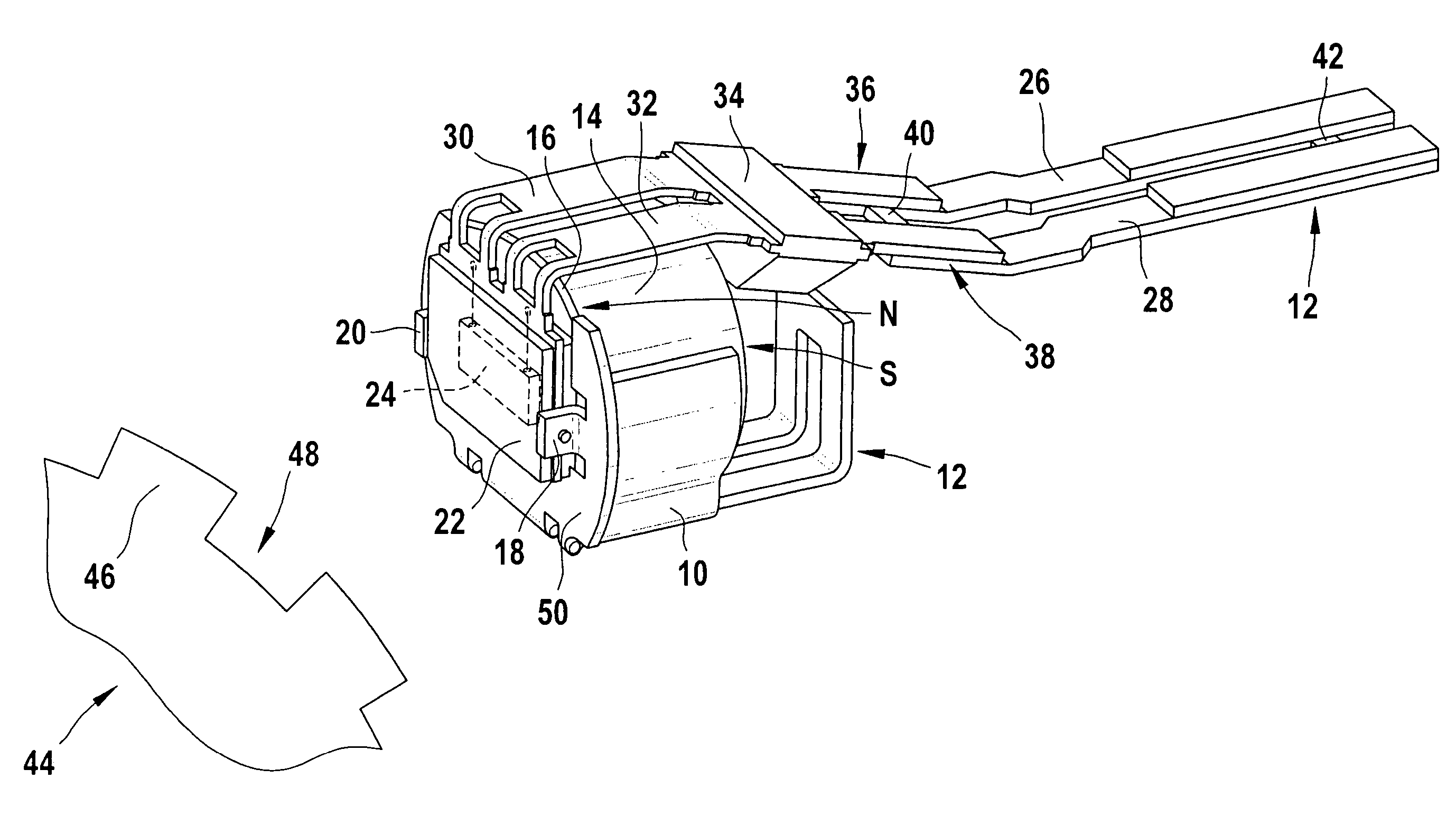
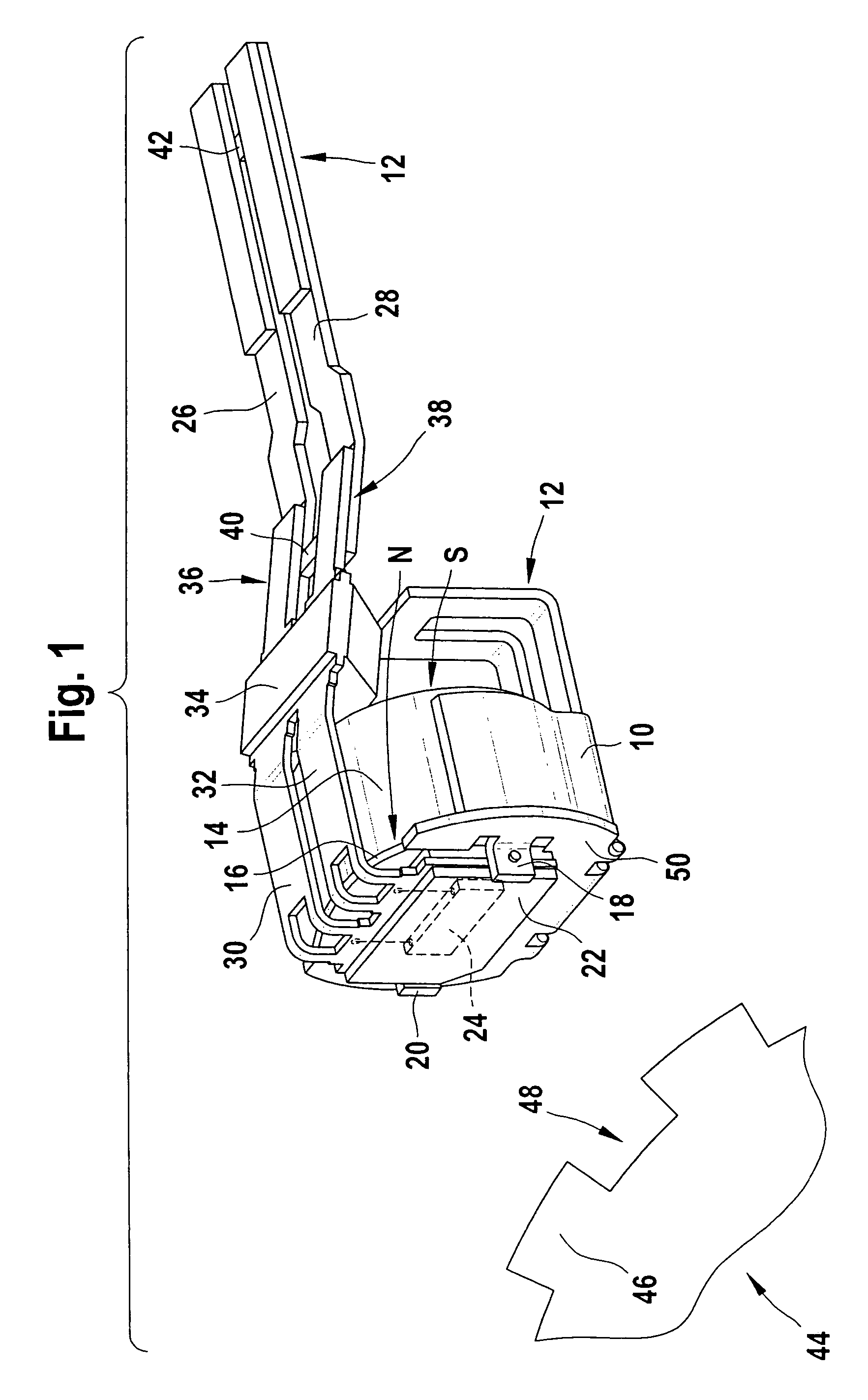
[0018]FIG. 1 shows a magnetic field sensor before it is sheathed with plastic, of the kind that can be used for instance as an rpm sensor and simultaneously as a rotational direction sensor for the transmission of a motor vehicle. Reference numeral 10 indicates a mount for the various components of the sensor, which is stamped out of a metal sheet of copper bronze (CuSn6) as a developed form of the mount 10 in the form of a flat stamped grid 12. A round or oval, axially magnetized permanent magnet 14 is seated in the mount and is located such that on its left-hand face end, it has a north pole (N), and on its right-hand face end it has a south pole (S). Seated inside the mount 10, on the north pole face end of the permanent magnet 14, is a scattering disk 16 of soft iron, which has only a slight thickness and is kept in saturation by the field of the magnet, so that the magnetic field is harmonized, and an extensively constant field intensity in the measurement region preceding the ...


PUM

PropertyMeasurementUnit
magnetic fieldaaaaaaaaaa
ferromagneticaaaaaaaaaa
magneticaaaaaaaaaa

Abstract

A magnetic field sensor, in particular an rpm sensor and / or rotational direction sensor and / or position sensor for the drive train of a motor vehicle, has a sensor array, with a sensor element that responds to a magnetic field, and optionally with a permanent magnet, the latter being sheathed with plastic jointly with the sensor array and parts of terminal conductor tracks, and the conductor tracks are embodied in one piece with a fixing element for the permanent magnet and the sensor array as a stamped grid, wherein stamped grid is shaped as a three-dimensional structure which carries the sensor array and optionally embraces the permanent magnet in the manner of a mount, and the mount and the terminal conductor tracks are first stamped out from a metal sheet as a gridlike developed form, and then deformed to form the mount.

Description

CROSS-REFERENCE TO RELATED APPLICATIONS[0001]This application claims priority under 35 U.S.C. 119 (a)-(d) to German Patent Application DE 10 2004 061 260.9 , filed Dec. 20, 2004.BACKGROUND OF THE INVENTION[0002]The invention relates to a magnetic field sensor, in particular an rpm sensor and / or a rotational direction sensor and / or a position sensor, preferably for the drive train of a motor vehicle, and to a method for producing such a sensor, of the kind disclosed for instance by European Patent Disclosure EP 0 898 180 A.[0003]This reference shows a frame for installing a magnetic field sensor that has crossbars for fixing a permanent magnet and also has a plurality of terminal conductor tracks for a sensor array, which in turn upon installation and with a later plastic potting rests on a flat portion of the frame. Such an arrangement on the one hand fails to assure exact positioning of the sensor components and on the other fails to provide an exact association between the permane...

Claims


Application Information

Patent Timeline
Patent Type & Authority Patents(United States)
IPC IPC(8): G01P3/42
CPCG01D11/245G01P1/026G01P3/488Y10T428/32
Inventor BRAUN, ALEXANDERHERZBERGER, ANDREASWALDENMEIER, STEFFEN
Owner ROBERT BOSCH GMBH
Why Eureka
Try Eureka