Method for joining structural material, joining sheet, and joint structure

a structural material and joint structure technology, applied in the direction of soldering equipment, furnaces, heat treatment equipment, etc., can solve the problems of difficult to join the members together in a short time, and high temperature, and achieve easy destruction by external stress, short time, and deteriorating resistance to stress

Active Publication Date: 2019-09-17
MURATA MFG CO LTD
View PDF40 Cites 4 Cited by
  • Summary
  • Abstract
  • Description
  • Claims
  • Application Information

AI Technical Summary

Benefits of technology

[0008]The joining method described in Patent Document 1 is a technique of joining a relatively small electronic part to a substrate, and joins two metal members together with an alloy joint layer interposed between the metal members. However, in this method, a joining temperature is high, and it is difficult to join the members together in a short time. Further, the above-mentioned alloy joint layer has weak points that are vulnerable to moisture and may be brittle depending on the material used. That is, a joint portion of two members is deteriorated with time and has deteriorating resistance to stress, and the joint portion may be easily destroyed by an external stress.
[0009]It is an object of the present invention to provide a method for joining structural materials together in which a high melting point intermetallic compound is produced in a short time at relatively low temperatures to obtain a joint structure with high reliability, a joining material and a joint structure.
[0014]In accordance with an aspect of the present invention, since the intermetallic compound layer of the low melting point metal and the high melting point metal is coated with a resin layer, a joint state of the first structural material and the second structural material can be easily stabilized. Further, since a joint layer having a substantially uniform thickness is formed throughout a space between the joint surfaces of the structural materials, the strength of the joint portion can be improved.

Problems solved by technology

However, in this method, a joining temperature is high, and it is difficult to join the members together in a short time.
Further, the above-mentioned alloy joint layer has weak points that are vulnerable to moisture and may be brittle depending on the material used.
That is, a joint portion of two members is deteriorated with time and has deteriorating resistance to stress, and the joint portion may be easily destroyed by an external stress.

Method used


Image

  • Method for joining structural material, joining sheet, and joint structure
  • Method for joining structural material, joining sheet, and joint structure
  • Method for joining structural material, joining sheet, and joint structure

Examples


first embodiment

[0029]A method for joining structural materials together, a joining material and a joint structure of a first embodiment will be described in reference to FIG. 1 to FIG. 4.

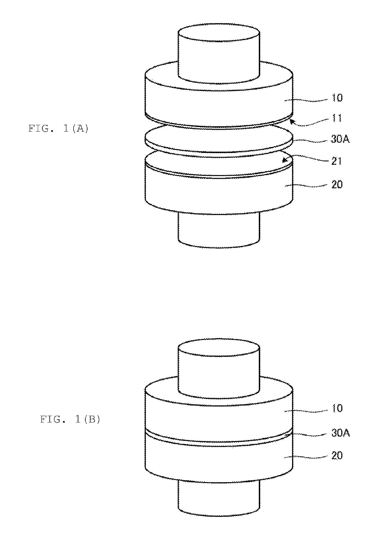
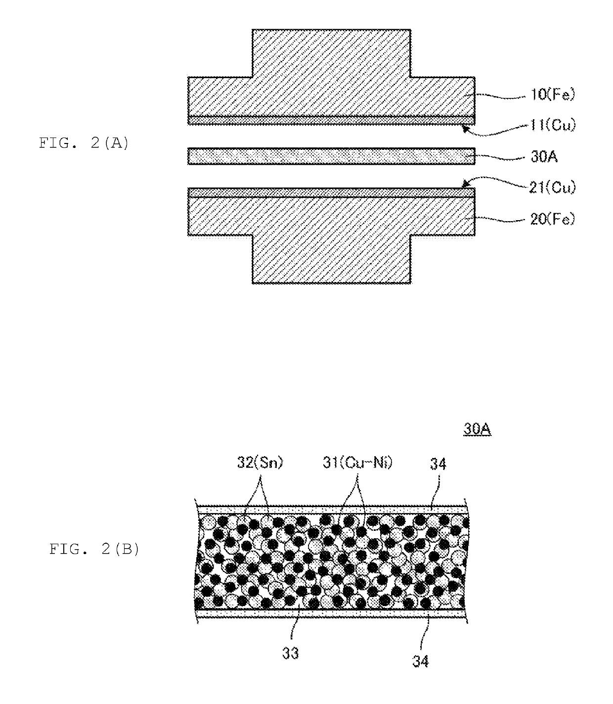
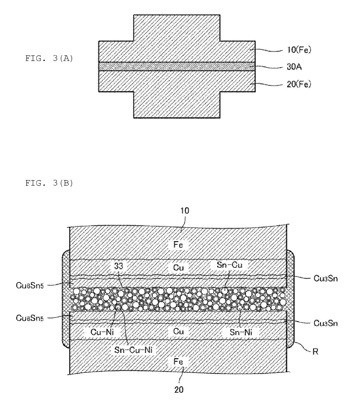
[0030]FIG. 1(A) is a perspective view showing a state before joining of a first structural material 10, a second structural material 20 and a joining material 30A to be joined together. FIG. 1(B) is a perspective view showing a state after joining. FIG. 2(A) is a sectional view showing a state before joining of a first structural material 10, a second structural material 20 and a joining material 30A to be joined together. FIG. 2(B) is an enlarged sectional view of the joining material. FIG. 3(A) is a sectional view showing a state after joining of a first structural material 10, a second structural material 20 and a joining material 30A. FIG. 3(B) is an enlarged sectional view of a joint portion.

[0031]The structural materials are scaffold materials of, for example, body frames, architectural structure, or machine...

second embodiment

[0053]A method for joining structural materials together, a joining material and a joint structure of a second embodiment will be described in reference with FIG. 5 and FIG. 6.

[0054]FIG. 5(A) is a sectional view showing a state before joining of a first structural material 10, a second structural material 20 and a joining material 30B to be joined together. FIG. 5(B) is an enlarged sectional view of the joining material. FIG. 6(A) is a sectional view showing a state after joining of a first structural material 10, a second structural material 20 and a joining material 30B. FIG. 6(B) is an enlarged sectional view of a joint portion.

[0055]The first structural material 10 is, for example, a steel material, and a plating film 12 of a Cu—Ni alloy which is a high melting point metal is formed on a joint surface. Similarly, the second structural material 20 is, for example, a steel material, and a plating film of a Cu—Ni alloy 22 is formed on a joint surface. In addition, when each structu...

third embodiment

[0070]A method for joining structural materials together, a joining material and a joint structure of a third embodiment will be described in reference with FIG. 7 and FIG. 8.

[0071]FIG. 7(A) is a sectional view showing a state before joining of a first structural material 10, a second structural material 20 and a joining material 30C to be joined together. FIG. 7(B) is an enlarged sectional view of the joining material. FIG. 8(A) is a sectional view showing a state after joining of a first structural material 10, a second structural material 20 and a joining material 30C. FIG. 8(B) is an enlarged sectional view of a joint portion.

[0072]The first structural material 10 is, for example, a steel material, and a Sn-plating film 13 which is a low melting point metal is formed on a joint surface. Similarly, the second structural material 20 is, for example, a steel material, and a Sn-plating film 23 is formed on a joint surface. In addition, when each structural material is, for example, ...


PUM

PropertyMeasurementUnit
softening temperatureaaaaaaaaaa
heat resistanceaaaaaaaaaa
areaaaaaaaaaaa

Abstract

A first structural material is bonded to a second structural material with a joining material provided with a mixed layer of a raw-material component for forming an intermetallic compound layer and a resin component that softens and flows during heat treatment interposed therebetween to form bonded structural materials. When the bonded structural materials are heat-treated, the first structural material is joined to the second structural material with an intermetallic compound layer, and the resin component exudes and covers the lateral circumferential (exposed) portion of the intermetallic compound layer with a resin film.

Description

CROSS REFERENCE TO RELATED APPLICATIONS[0001]The present application is a continuation of International application No. PCT / JP2015 / 050107, filed Jan. 6, 2015, which claims priority to Japanese Patent Application No. 2014-000959, filed Jan. 7, 2014, the entire contents of each of which are incorporated herein by reference.FIELD OF THE INVENTION[0002]The present invention relates to a method for joining structural materials having a large joint surface, a joining sheet and a joint structure which are respectively used for the joining.BACKGROUND OF THE INVENTION[0003]Soldering, spot welding, or brazing is used for joining structural materials having a large joint surface, such as a heatsink or an automotive body.[0004]Since a solder has properties of gathering in a place where wettability is high during heating and melting, it is difficult to join large joint surfaces together, and there is typically no other choice but to employ joining in the form of spot welding. Further, in the spo...

Claims


Application Information

Patent Timeline
Patent Type & Authority Patents(United States)
IPC IPC(8): B23K31/02B23K20/02C21D9/50B23K35/36B23K35/30B23K20/00B23K1/00
CPCB23K1/00B23K20/002B23K20/026C21D9/50B23K35/302B23K35/3613
Inventor ISHINO, SATOSHIKAWAGUCHI, YOSHIHIRONAKANO, KOSUKETAKAOKA, HIDEKIYOYANASE, WATARU
Owner MURATA MFG CO LTD
Why Eureka
Try Eureka