

Display medium, display device, and displaying method
a technology of display medium and display medium, which is applied in the direction of static indicating devices, instruments, optics, etc., can solve the problems of difficult to reduce the thickness and weight of the medium, the promising methods for displaying systems of electronic paper have yet to be established, and the thickness of the medium is difficult to redu
- Summary
- Abstract
- Description
- Claims
- Application Information
AI Technical Summary
Benefits of technology
Problems solved by technology
Method used
Image

Examples
example 1
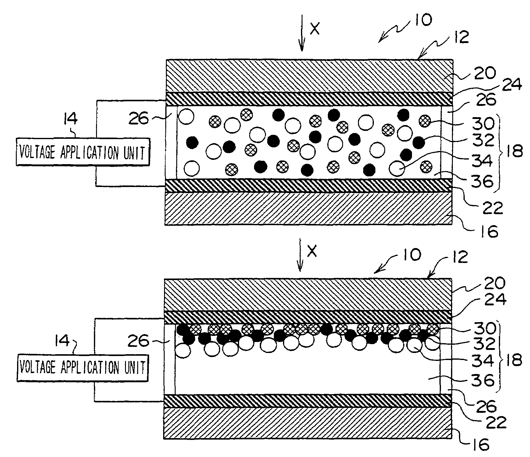
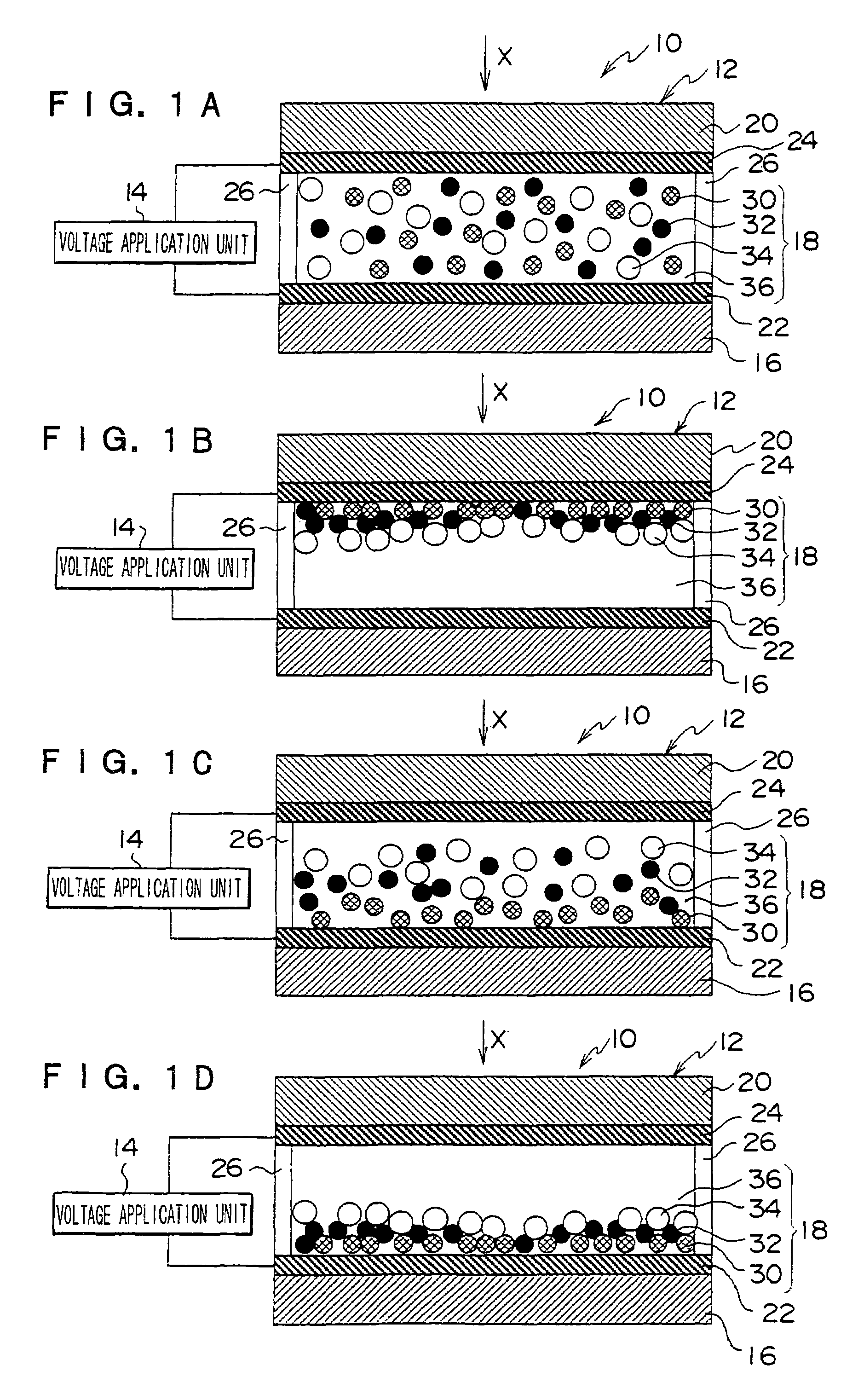
[0248]An example of the display medium according to an aspect of the invention will be described with reference to FIGS. 3A to 3D.
[0249]First, a first ITO electrode 22 is formed to a thickness of 50 nm on a glass rear-face substrate 16 having a thickness 0.7 mm by sputtering, and the electrode is patterned into lines by photolithography and dry etching (line width: 300 μm).
[0250]Then, a barrier layer is formed on the rear-face substrate 16 carrying the first electrode 22 by coating a photosensitive polyimide varnish, and the layer is exposed to light and wet-etched to form multiple spacers 26 having a height of 50 μm and a width of 20 μm.
[0251]Separately, a second ITO electrode 24 is formed to a thickness of 50 nm on a polyethylene terephthalate (PET) display substrate 20 having a thickness of 200 μm by sputtering, and patterned into lines by photolithography and dry etching. The line width is approximately 300 μm.
[0252]A hot-melt adhesive layer is formed on the contact areas betwee...
example 2
[0272]In a similar manner to Example 1, another example of the display medium 13 according to an aspect of the invention will be described in Example 2 with reference to FIGS. 3A to 3D. The difference in the mobility of the particles contained in the light-modulating layer 19 (3.2×10⁻⁶ cm2 / Vs) is different from that in Example 1.
[0273]In Example 2, a display medium 13 is prepared in a similar manner to Example 1, except that the differences in mobility among the charged mobile particles 30, the first particles 32, and the second particles 34 are different from those in Example 1.
[0274]In a similar manner to Example 1, the voltage application unit 14 used is FG110 manufactured by Yokogawa Electric Corporation.
[0275]The content of the colloidal silver particles in the aqueous colloidal silver dispersion liquid is 1.0 wt %; the volume fraction of the colloidal silver particles in the light-modulating layer 19 is 1.0 vol %; the volume fraction of the black particle as first particles is...
example 3
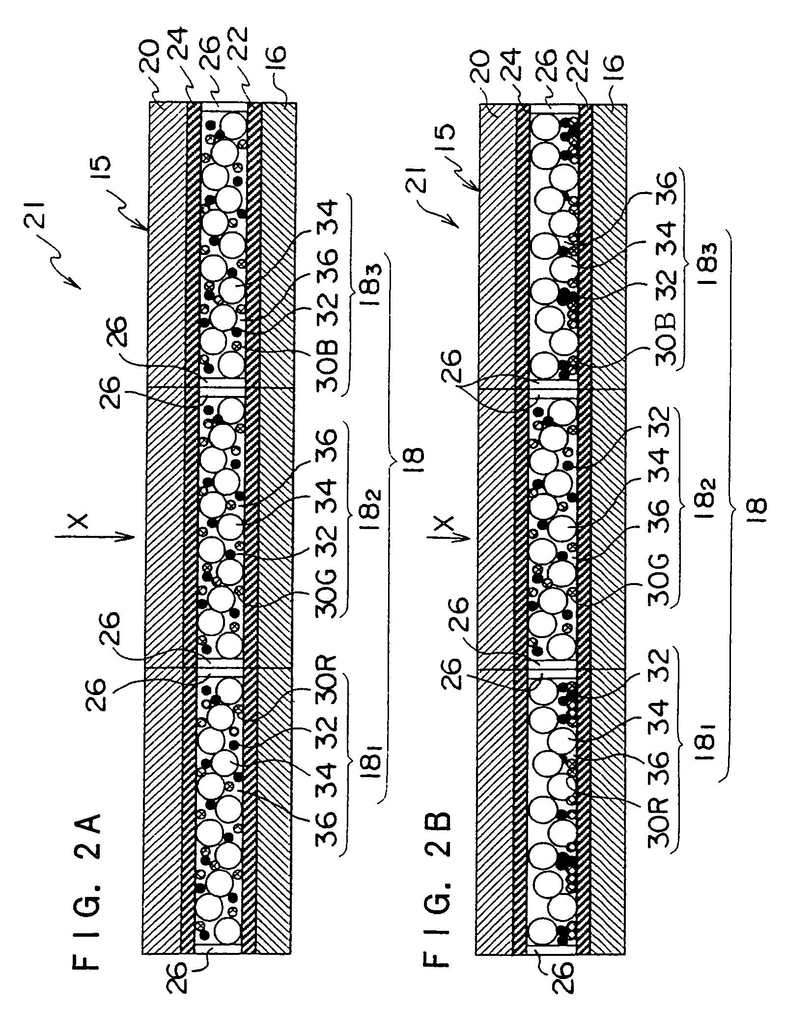
[0289]An example of the display medium according to an aspect of the invention will be described with reference to FIGS. 2A and 2B.
[0290]First, a first ITO electrode 22 is formed to a thickness of 40 nm on a glass rear-face substrate 16 having a thickness 0.7 mm by sputtering, and the electrode is patterned into lines by photolithography and dry etching at an interval of 20 μm (electrode line width: 200 μm, distance between first electrodes 22: 20 μm).
[0291]Separately, an ITO second electrode 24 is formed on a polyethylene terephthalate (PET) display substrate 20 having a thickness of 200 μm, and patterned into lines by photolithography and dry etching, at an interval of 20 μm (electrode line width: 200 μm, distance between first electrodes 22: 20 μm).
[0292]Then, a barrier layer is formed on the rear-face substrate 16 carrying the first electrode 22 by coating a photosensitive polyimide varnish, and the layer is exposed to light and wet-etched to form multiple spacers 26 having a he...
PUM
| Property | Measurement | Unit |
|---|---|---|
| volume average particle diameter | aaaaa | aaaaa |
| volume average particle diameter | aaaaa | aaaaa |
| pH | aaaaa | aaaaa |
Abstract
Description
Claims
Application Information