
Superconductive stripline filter utilizing one or more inter-resonator coupling members

a superconductive and coupling member technology, applied in the direction of basic electric elements, electrical equipment, waveguides, etc., can solve the problems of bandwidth either increasing or decreasing, bandwidth changes as well, and the above scheme exhibits another drawback, so as to achieve the effect of stabilizing bandwidth during tuning

Inactive Publication Date: 2009-10-27
SUPERCONDUCTOR TECHNOLOGIES INC
View PDF51 Cites 3 Cited by
  • Summary
  • Abstract
  • Description
  • Claims
  • Application Information

AI Technical Summary

Benefits of technology

[0009]A preferred embodiment of an apparatus constructed according to the principles of the present invention includes an inter-resonator coupling scheme for a filter. The filter preferably includes at least two resonators. An inter-resonator coupling member is located between successive resonators in the filter. Preferably, the coupling member is located adjacent an edge portion of the resonator which is distal from that portion of the resonator over which a tuning tip is located. By then adjusting the length and / or the proximity of the inter-resonator coupling member relative to the adjacent resonators, the ratio of energy transferred from resonator to resonator (via the inter-resonator coupling member) may be increased and / or decreased. By increasing the ratio of energy transferred from resonator to resonator, the bandwidth of the filter is increased and is made relatively insensitive to tuning which may occur via manipulation of field disturbances introduced by tuning tips.
[0012]According to yet another aspect of the present invention, there is provided a method of stabilizing bandwidth during tuning of a filter comprising at least first and second resonators, wherein the energy is transferred from the first resonator to the second resonator when a signal is introduced to the first resonator, and wherein the filter is tuned by introducing a field disturbance proximate at least the first resonator, the method comprising: providing a coupling member interposed between the first and second resonators, wherein the coupling member transfers a greater quantity of energy from the first resonator to the second resonator than is transferred via a propagation path passing proximate the field disturbance.

Problems solved by technology

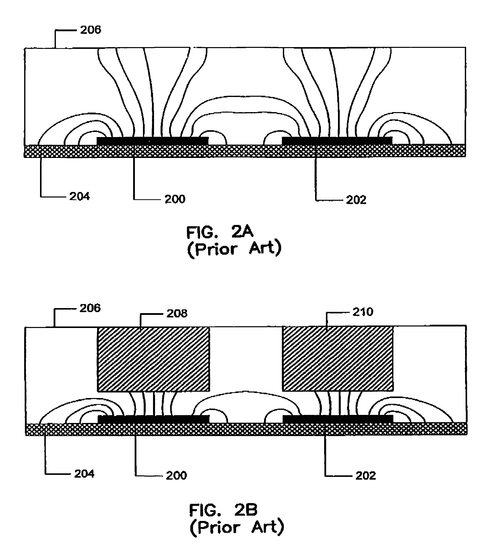
One particular drawback of such a scheme is that as the tuning tips 208 and 210 are adjusted for the sake of tuning the center frequency of the filter, the bandwidth of the filter changes as well.
Thus, bringing a tuning tip into closer proximity to a resonator may cause the bandwidth to either increase or decrease, depending upon the design of the filter.
The aforementioned scheme exhibits another drawback.
Unfortunately, because the tuning tips are to be located over the resonators, varying inter-resonator spacing means that a different conductive cover must be fabricated for each communication scheme.
It will be appreciated, however, that it is generally undesirable to require different conductive covers for each communication scheme (e.g., because the numbers of parts are proliferated and costs are raised).

Method used


Image

  • Superconductive stripline filter utilizing one or more inter-resonator coupling members
  • Superconductive stripline filter utilizing one or more inter-resonator coupling members
  • Superconductive stripline filter utilizing one or more inter-resonator coupling members

Examples


Embodiment Construction

[0024]The principles of the present invention apply particularly well to its application in a filter application for electromagnetic waves. Such filters generally include a plurality of resonators. One environment in which such filters are commonly employed is in cellular telephone communication systems. However, such environment is illustrative and should not be viewed in a limiting manner.

[0025]Turning now to FIGS. 4A, 4B, and 4C, such Figures depict a filtering scheme, constructed in accordance with the principles of the present invention, that addresses the drawbacks of the prior art. The filters depicted in FIGS. 4A, 4B, and 4C may operate in an environment similar to the one discussed above with reference to FIGS. 2A and 2B (i.e., the resonators may be made of similar materials, may reside atop a substrate made of similar material, and may be housed in a metallic cavity, etc.). FIG. 4A depicts a filter scheme that has a bandwidth of 5 MHz. FIGS. 4B and 4C depict filter schemes...


PUM


Abstract

An inter-resonator coupling scheme for a filter is disclosed. An inter-resonator coupling member is located between successive resonators in the filter. By adjusting the length and / or the proximity of the inter-resonator coupling member relative to the adjacent resonators, the ratio of energy transferred from resonator to resonator (via the inter-resonator coupling member) may be increased and / or decreased. By increasing the ratio of energy transferred from resonator to resonator, the bandwidth of the filter is increased and is made relatively insensitive to tuning which may occur via manipulation of field disturbances introduced by tuning tips. The inter-resonator coupling member is made of a conductive or superconductive material and contains at least three sections. The first section runs substantially parallel to an edge of the first resonator that is not profoundly influenced by the source of field disturbance. The third section runs substantially parallel to an edge of the second resonator that is not profoundly influenced by the source of field disturbance. A second section connects the first and third sections.

Description

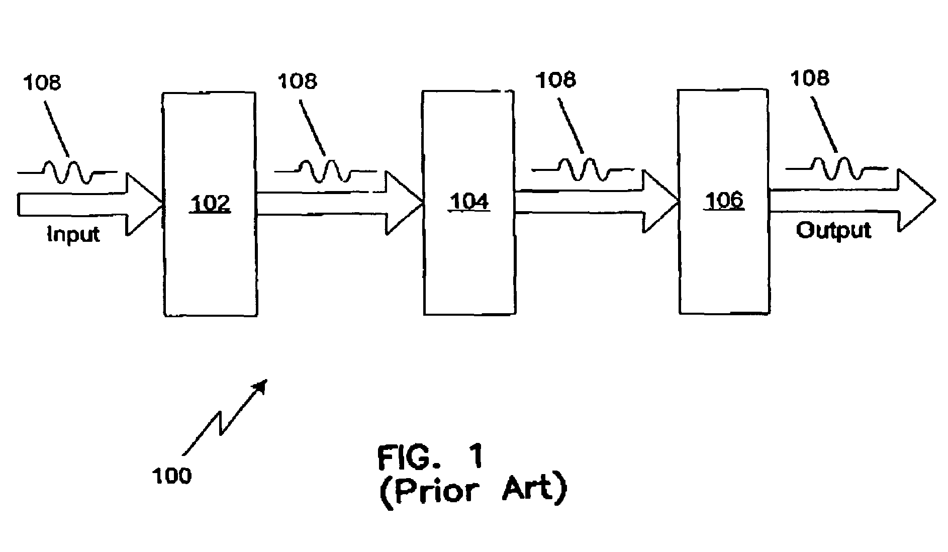
CROSS-REFERENCE TO RELATED APPLICATION[0001]This application claims the benefit of U.S. Provisional Application Ser. No. 60 / 504,578, filed on Sep. 18, 2003 entitled STRIPLINE FILTER UTILIZING ONE OR MORE INTER-RESONATOR COUPLING MEANS. Such application is incorporated herein by reference.FIELD OF THE INVENTION[0002]The invention relates generally to a stripline filter utilizing one or more inter-resonator coupling members, and more particularly to a high temperature superconductive planar stripline or microstrip circuit that utilizes one or more inter-resonator coupling members to preserve bandwidth while allowing filter tuning.BACKGROUND[0003]In the field of stripline filter design, it is commonplace to employ a filter scheme as generally shown in FIG. 1. FIG. 1 depicts a filter 100 having three resonators 102, 104 and 106, an Input and an Output. Although the filter 100 is depicted as having three resonators, the filter 100 could possess any number of resonators, in principle. An ...

Claims


Application Information

Patent Timeline
IPC IPC(8): H01P1/203H01B12/02H01P1/213H04B1/10
CPCH01P1/20381H01P1/20336
Inventor YE, SHEN
Owner SUPERCONDUCTOR TECHNOLOGIES INC
Learn More