Data processing system, data processing method and storage apparatus

a data processing system and data processing method technology, applied in the field of raid (redundant array of inexpensive disks), can solve the problems of reducing the service life of the storage apparatus, and unable to add spare disks, so as to achieve the maintenance of failure resistance, the effect of long-term maintenance and maintenan

Inactive Publication Date: 2009-10-27
HITACHI LTD
View PDF18 Cites 9 Cited by
  • Summary
  • Abstract
  • Description
  • Claims
  • Application Information

AI Technical Summary

Benefits of technology

[0010]With the data processing system according to this invention, because a spare memory area can be dynamically reserved from among the memory areas of existing disks, the data processing system can be compact, can be used for a long time, and its failure resistance can be maintained.
[0012]With the data processing method according to this invention, because a spare memory area can be dynamically reserved from among the memory areas of existing disks, failure resistance can be maintained for a compact data processing system suitable for long-term use.
[0014]According to this invention, because a spare memory area can be dynamically reserved from among the memory areas of existing disks, a storage apparatus can be compact and used for a long time and the failure resistance can be maintained.
[0015]According to this invention, spare disks or spare areas can be reserved without mounting many disks or replacing disks, thereby enabling the maintenance of the failure resistance of a compact data processing system or storage apparatus suitable for long-term use.

Problems solved by technology

Accordingly, with storage apparatuses incapable of disk replacement (hereinafter called ‘non-replaceable disk storage apparatuses’, there is a problem in that spare disks cannot be added and failure resistance degrades.
Although it is possible to mount as many spare disks as possible in non-replaceable disk storage apparatuses, it increases the cost and the size of the storage apparatuses.

Method used


Image

  • Data processing system, data processing method and storage apparatus
  • Data processing system, data processing method and storage apparatus
  • Data processing system, data processing method and storage apparatus

Examples


embodiment 1

1. Embodiment 1

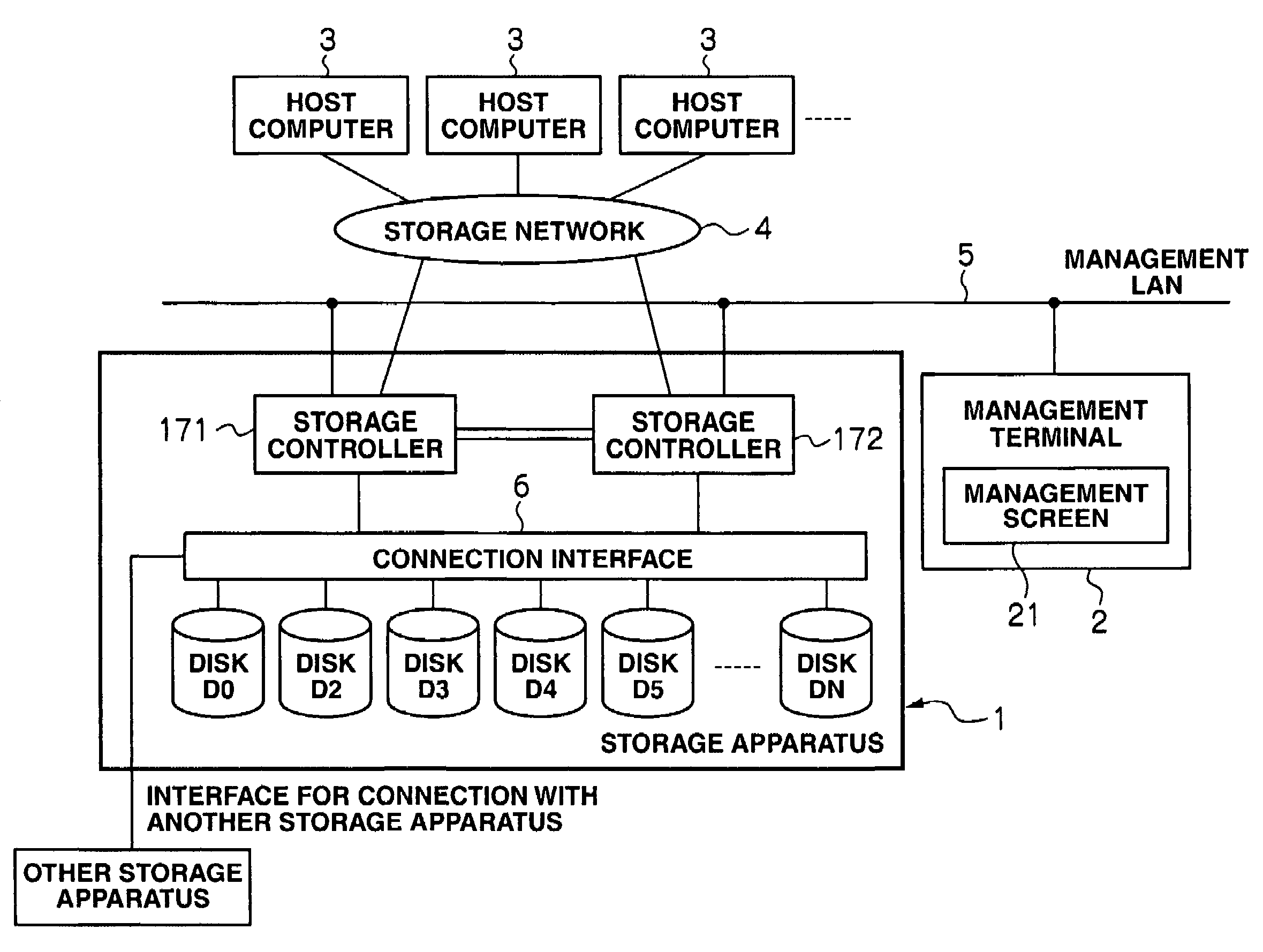
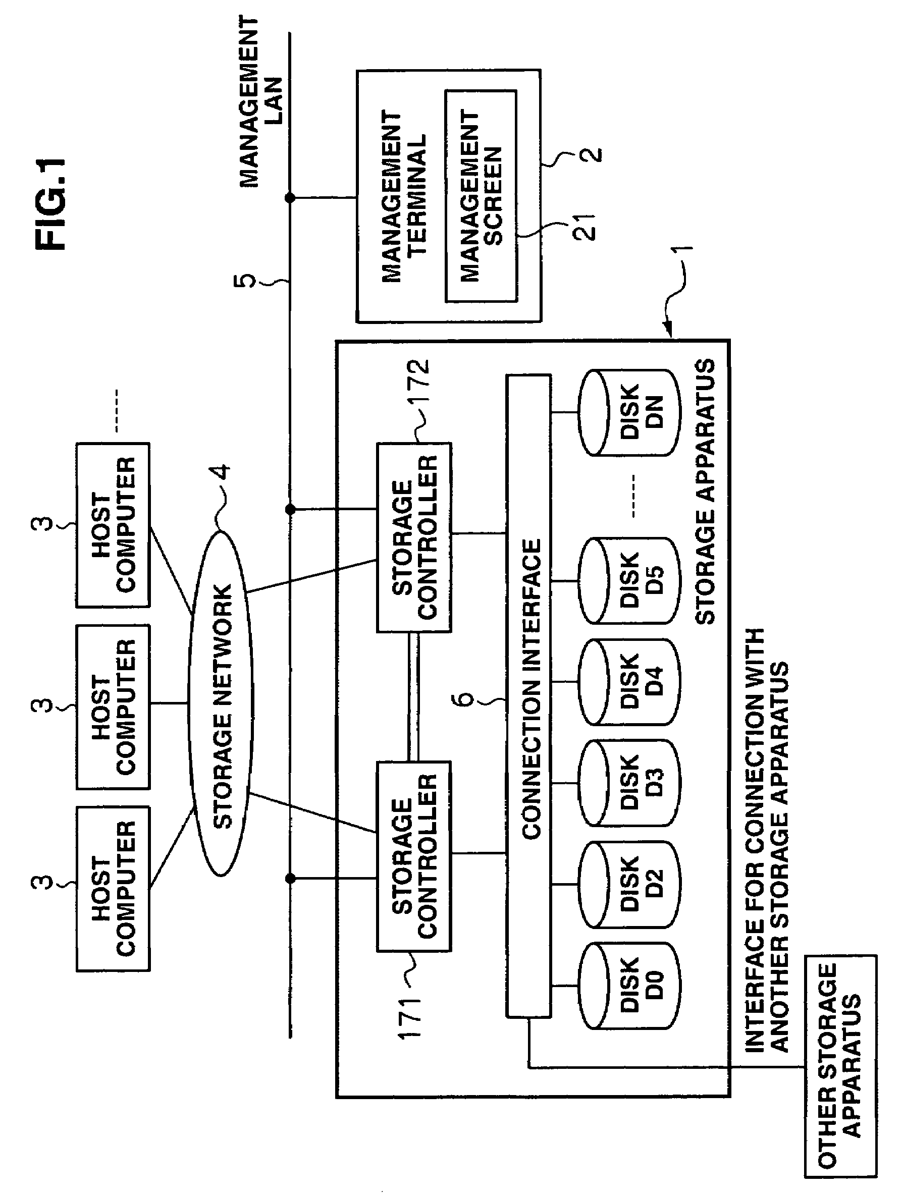
[0053]FIG. 1 shows the structure of a storage apparatus according to Embodiments 1 to 4 of this invention. The storage apparatus 1 is connected to a management terminal 2 via a management LAN 5. It is also connected to a plurality of host computers 3 via a storage network 4. It has a connection interface 7 for connection with a replacement storage apparatus.

[0054]The storage apparatus 1 also has storage controllers 171 and 172 so that a large amount of data can be input / output from / to the storage network at a time.

[0055]Incidentally, there may be any number of storage controllers, depending on the type of embodiment.

[0056]The storage apparatus 1 also includes a plurality of disks D0, D1, D2 . . . DN. The storage controllers 171 and 172 are connected to these disks D0 to DN via a connection interface 6. Accordingly, the storage controllers 171 and 172 and disks D0 to DN input / output data to each other. The connection between the storage controllers 171 and 172 and disk...

embodiment 2

2. Embodiment 2

[0127]Embodiment 2 of this invention is a method for reserving a new spare disk by changing the RAID level in the storage apparatus 1. For example, RAID-6 (nD+2P) configuration is changed to RAID-5 (nD+1P) configuration to make the disk left in this change a spare disk. This embodiment is explained with reference to FIGS. 20 to 23.

[0128]FIG. 20 is a flowchart showing failure recovery and next-spare-disk reservation processing the CPU 1901 performs based on the control program 1903 and management table 1904 when a disk failure occurs, according to Embodiment 2.

[0129]Steps S1000 to S1012 and steps S100 to S102 are the same as those in Embodiment 1 above, so their explanations have been omitted.

[0130]If no spare disk is found in the second spare disk search (S1012: No), the CPU 1901 refers to the RAID information management table T2 to judge whether there is a RAID group whose RAID level can be changed, and if there is one (S4100: Yes), it changes its RAID level (S4101)....

embodiment 3

3. Embodiment 3

[0140]Embodiment 3 of this invention is a method for reserving a spare area as an LU, not as a disk. In Embodiments 1 and 2, the data content of a faulty disk is rebuilt in a physical disk, however, in Embodiment 3, it is rebuilt in an LU, i.e., in a logical disk. A method for reserving an LU as a spare area (hereinafter called a ‘spare LU’) has an advantage over Embodiments 1 and 2 in that the spare area can be easily reserved without having to move the existing data blocks. However, because access is made by changing an original LU address (LBA) in a faulty disk to an address in a spare LU, the performance may be inferior to that in Embodiments 1 and 2. Embodiment 3 is explained with reference to FIGS. 24 to 27.

[0141]FIG. 24 is an explanatory diagram showing the control program 1903 and management table 1904 stored in the memory 1902, according to Embodiment 3.

[0142]The control program 1903 according to Embodiment 3 is composed of a RAID control program 1911, RAID g...


PUM


Abstract

A compact data processing system suitable for long-term use that enables the maintenance of failure resistance without having to mount many spare disks or replace disks; a data processing method; and a storage apparatus for this data processing system are provided. In the data processing system, which has a host system and a storage apparatus that provides first memory areas for storing data read / written by the host system, the storage apparatus has a reservation unit that dynamically reserves one of the first memory areas as a spare second memory area when a failure occurs in any one of the first memory areas and there is no spare second memory area to migrate the data stored in that faulty memory area to.

Description

CROSS-REFERENCES TO RELATED APPLICATIONS[0001]This application relates to and claims priority from Japanese Patent Application No. 2006-180256, filed on Jun. 29, 2006, the entire disclosure of which is incorporated herein by reference.BACKGROUND[0002]1. Field of the Invention[0003]The invention relates to a RAID (Redundant Array of Inexpensive Disks) configuration-adopting data processing system, data processing method, and storage apparatus; particularly to a data processing system, data processing method and storage apparatus where some or all disk drives (hereinafter simply referred to as ‘disks’) are non-replaceably mounted.[0004]2. Description of Related Art[0005]Conventionally, there have been storage apparatuses where RAID configurations are adopted as prevention measure against data loss resulting from disk failures (see, for example, the non-patent document “A Case for Redundant Arrays of Inexpensive Disks (RAID)” by David A. Patterson, Garth Gibson, and Randy H. Katz, Univ...

Claims


Application Information

Patent Timeline
Patent Type & Authority Patents(United States)
IPC IPC(8): G06F11/00
CPCG06F11/1084G06F11/2094G06F11/1662G06F2211/1028
Inventor ARAI, MASAHIRO
Owner HITACHI LTD
Why Eureka
Try Eureka