Guide for the precise control of portable power tools

a portable power tool and guide technology, applied in the direction of chain saws, metal sawing accessories, manufacturing tools, etc., can solve the problems of affecting the operation of the operator or an errant cut, the tool guide functions like a panel saw but is portable and lightweight, and the design is more costly to produce, so as to prevent the tool from vibrating loose, easy to construct, and effective locking the cam lock

Inactive Publication Date: 2009-11-03
BESSETTE BERNARD J
View PDF25 Cites 21 Cited by
  • Summary
  • Abstract
  • Description
  • Claims
  • Application Information

AI Technical Summary

Benefits of technology

[0023]Configuring the trolley with multiple guideposts, or the two guide blocks, ensures that the trolley captures the segmented guide rail throughout all phases of the cut. A minimum of two leading guideposts, at least one near the center of the trolley and two at the rear of the trolley in the first embodiment, function to keep the chassis in alignment with the cut-line. When the chassis is placed upon the front edge of the workpiece, the two leading guideposts or the forward guide block capture the segmented guide rail establishing the initial alignment of the chassis to the cut-line before the tool is started and engages the workpiece. The trailing guideposts or guide block maintain the tool in alignment at the point where the cutter breaks free of the workpiece at the end of the cut. In both embodiments of the invention, the chassis fully contains the tool base and the chassis is fully supported by the workpiece; which prevents any tilting or rotational movement caused by lateral forces applied during operation, thereby avoiding binding or kick-back. The device of U.S. Pat. No. 5,815,931, for instances, captures only one edge of the saw base creating a condition that enables the saw to tilt during operation if a downward force is applied to the rear of the saw while operating. This can cause binding or kick-back and result in danger to the operator or an errant cut. Multiple segments of the guard rail can be joined together to accommodate various lengths of workpieces for no restriction in length of travel. The segmented guide rail controls the direction of the tool guide and does not require either parallel or straight edges on the workpiece in order to produce straight cuts and it facilitates making angular cuts across the workpiece. The segmented guide rail is clamped to the workpiece using conventional C-clamps or fast action spring clamps or any other suitable clamp for simplicity and ease of use. The segmented guide rail does not include intricate integral clamps that make the design more costly to produce, which would also preclude the joining of additional sections when needed to rip long workpieces.
[0024]The reference distance representing the offset from the guide rail to the saw blade or cutter is a constant for each tool and is taken into account when positioning the segmented guide rail to align the tool to the cut-line. This is a fixed dimension and is unique for each tool or cutter combination. My tool guide provides a positive means of controlling circular saws, saber saws and routers along a defined cut-line without needing to have the cut-line in sight or having to have rigid control of the tool and as a result there is ease of cut, no binding, kickback or errant cuts. The operator can operate the tool with either their right or left hands and can make ripping cuts down the center of a 4 by 8 foot sheet of plywood or other large sheets of work stock with ease. My tool guide functions like a panel saw but is portable and lightweight.

Problems solved by technology

This can cause binding or kick-back and result in danger to the operator or an errant cut.
The segmented guide rail does not include intricate integral clamps that make the design more costly to produce, which would also preclude the joining of additional sections when needed to rip long workpieces.
My tool guide functions like a panel saw but is portable and lightweight.

Method used


Image

  • Guide for the precise control of portable power tools
  • Guide for the precise control of portable power tools
  • Guide for the precise control of portable power tools

Examples


Embodiment Construction

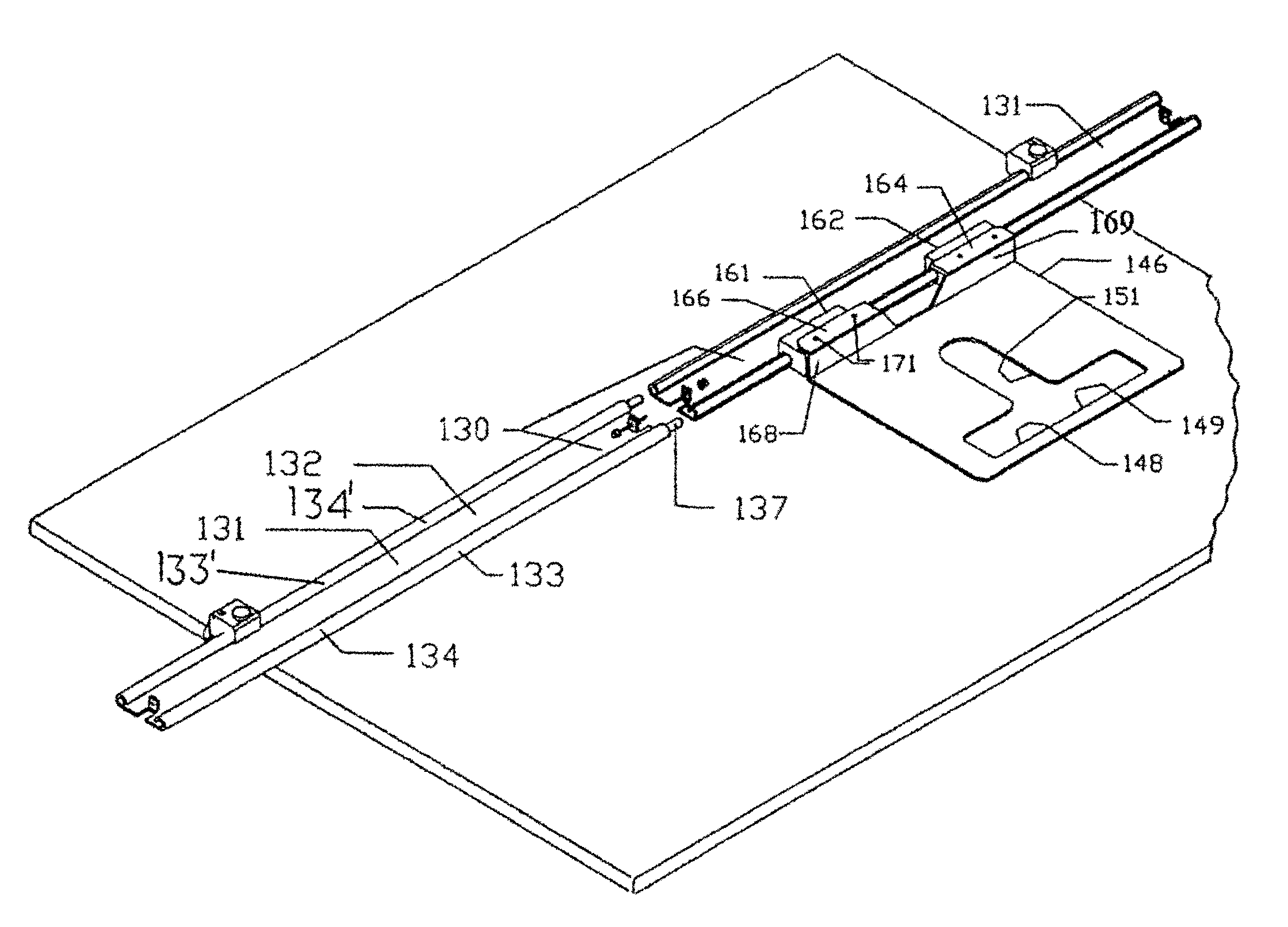
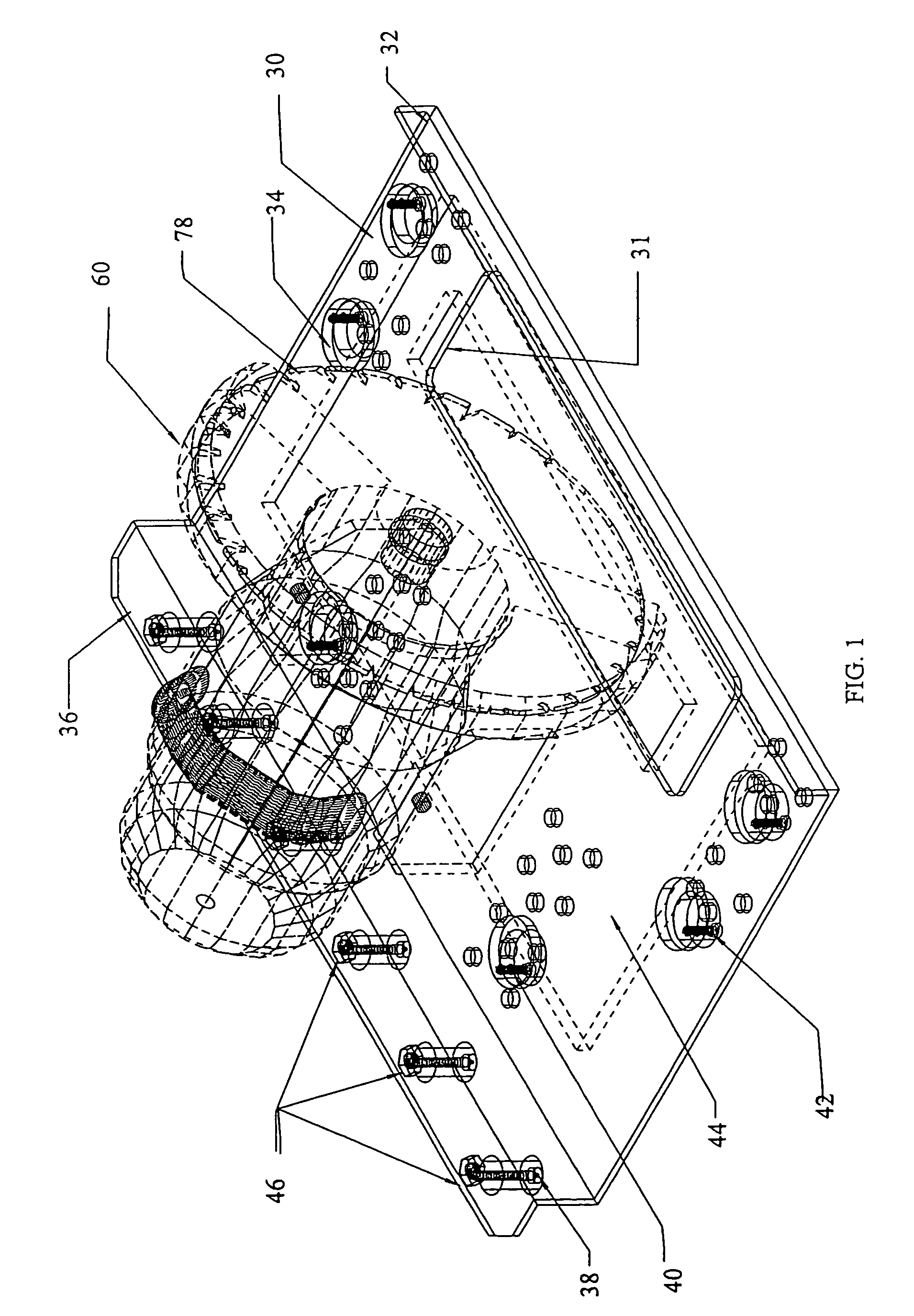
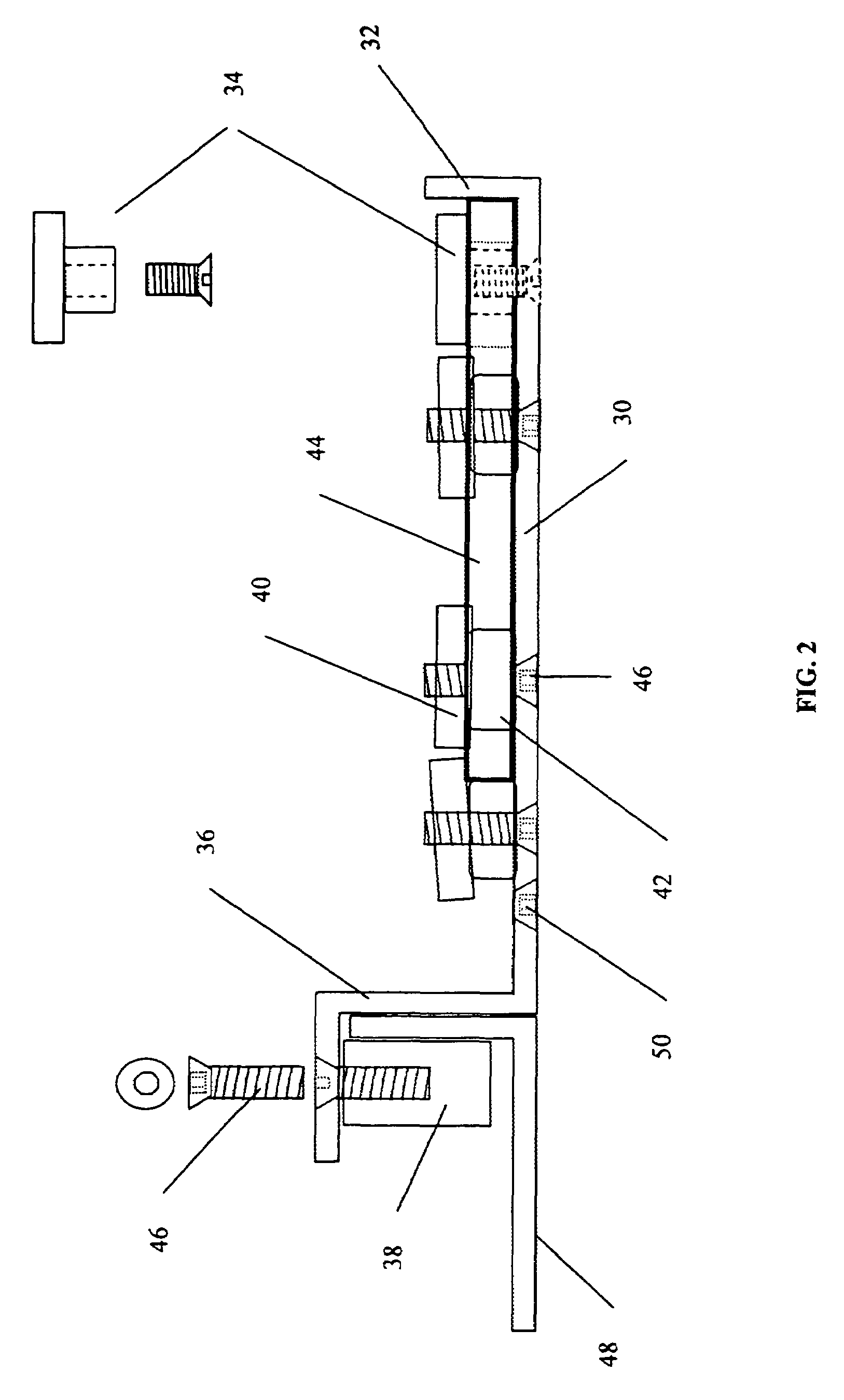
[0052]Several embodiments of the tool guide for portable power tools are illustrated in the accompanying drawings. The set up and operation of the tool guide for precise control of portable power tools, such as circular saws, saber saws and routers is closely related. Referring to FIGS. 1 through 8, a chassis 30, to which the power saw 60, or other cutting tool, is attached, is fabricated using light weight, one-piece sheet aluminum, but can be made from malleable metal, cast or molded material. The chassis 30 includes a flat panel 30′ with a cutout 31 through which a cutter or blade protrudes and a series of countersunk holes 50, spaced to accommodate various tool plates such as tool plate 44. Fixed stops 34, cam lock disks 40 and compression spacers 42 are provided for the securing and tensioning the power tool mounting plate 44 to the chassis 30; and a perpendicular vertical edge that forms an upstanding reference edge 32 is provided on the chassis for precise alignment of the cu...


PUM

PropertyMeasurementUnit
lengthaaaaaaaaaa
lengthaaaaaaaaaa
distanceaaaaaaaaaa

Abstract

A tool trolley or guide for the precise control of hand held power tools such as a circular saw, saber saw, router or other portable power tool to guide the tool along a straight guide path. A chassis upon which the power tool is attached has a trolley like connection with a guide rail releasably secured to a work piece. The chassis has an opening through which the cutters of the tool extend. Tools are mounted on mounting plates which in turn are releasably mounted on the chassis.

Description

RELATED APPLICATIONS[0001]This application is a continuation-in-part of U.S. patent application Ser. No. 10 / 303,538 filed Nov. 25, 2002 now abandoned for a Tool Trolley Guide for the Precise Control of Portable Power Tools.BACKGROUND OF THE INVENTION[0002]Power tools such as circular saws, saber saws and routers are used for cutting, ripping, plowing rabbets and dados and shaping wood and other materials. Each of these tools require the operator to have firm control of the tool and unobstructed view of the cut-line in order to produce a straight and accurate cut along a prescribed cut-line during operation. All of these tools produce significant amounts of sawdust that obscures the cut-line. In addition, any variation in the amount of force applied to the tool as well as normal wear factors such as dulling of saw teeth or cutter edges and varying alignment in the teeth of the saw blades, causes the cutter or blade to drift resulting in binding, kickbacks and errant cuts. In addition...

Claims


Application Information

Patent Timeline
Patent Type & Authority Patents(United States)
IPC IPC(8): B26D5/00
CPCB23Q9/0014Y10T83/667Y10T83/68Y10T83/75Y10T83/7763
Inventor BESSETTE, BERNARD J.
Owner BESSETTE BERNARD J
Why Eureka
Try Eureka