Method and system to facilitate enhanced local cooling of turbine engines

a technology of local cooling and turbine engines, applied in the field can solve the problems of affecting the efficiency of gas turbine engines, reducing service life and/or material failure, adversely affecting component clearance and/or component inter-fitting relationships,

Active Publication Date: 2009-11-03
GENERAL ELECTRIC CO
View PDF15 Cites 6 Cited by
  • Summary
  • Abstract
  • Description
  • Claims
  • Application Information

AI Technical Summary

Benefits of technology

[0007]In one aspect, a method of assembling a gas turbine engine is provided. The method includes coupling at least one turbine nozzle segment within the gas turbine engine. The at least one turbine nozzle segment includes at least one airfoil vane extending between an inner band and an outer band that includes an aft flange and a radial inner surface. The method also includes coupling at least one turbine shroud segment downstream from the at least one turbine nozzle segment, wherein the at least one turbine shroud segment includes a leading edge and a radial inner surface, coupling a cooling fluid source in flow communication with the at least one turbine nozzle segment such that cooling fluid channeled to each turbine nozzle outer band aft flange is directed at an oblique discharge angle towards the leading edge of the at least one turbine shroud segment, and channeling the cooling fluid through at least a first group of cooling openings having a larger aggregate cross-sectional area and a second group of cooling openings having a smaller aggregate cross-sectional area to facilitate preferential cooling of the turbine shroud.

Problems solved by technology

However, as operating temperatures are increased, the thermal limits of certain engine components may be exceeded, resulting in reduced service life and / or material failure.
Moreover, the increased thermal expansion and contraction of components may adversely affect component clearances and / or component interfitting relationships.
Gas turbine engine efficiency may be negatively affected by a fluctuation in turbine blade tip clearance measured between a radially outer surface of the turbine blade and a radially inner surface of the shroud assembly.
When the difference in the rotor blade radial displacement and the shroud assembly radial displacement is too great, the blade tip clearance is increased, which may result in reducing engine efficiency.
This circumferential gas pressure variation may cause localized hot gas ingestion into the gap between the outer band and the shroud segment.
As a result, cooling air flowing through the gap may not effectively cool the downstream shroud segment.

Method used


Image

  • Method and system to facilitate enhanced local cooling of turbine engines
  • Method and system to facilitate enhanced local cooling of turbine engines
  • Method and system to facilitate enhanced local cooling of turbine engines

Examples


Embodiment Construction

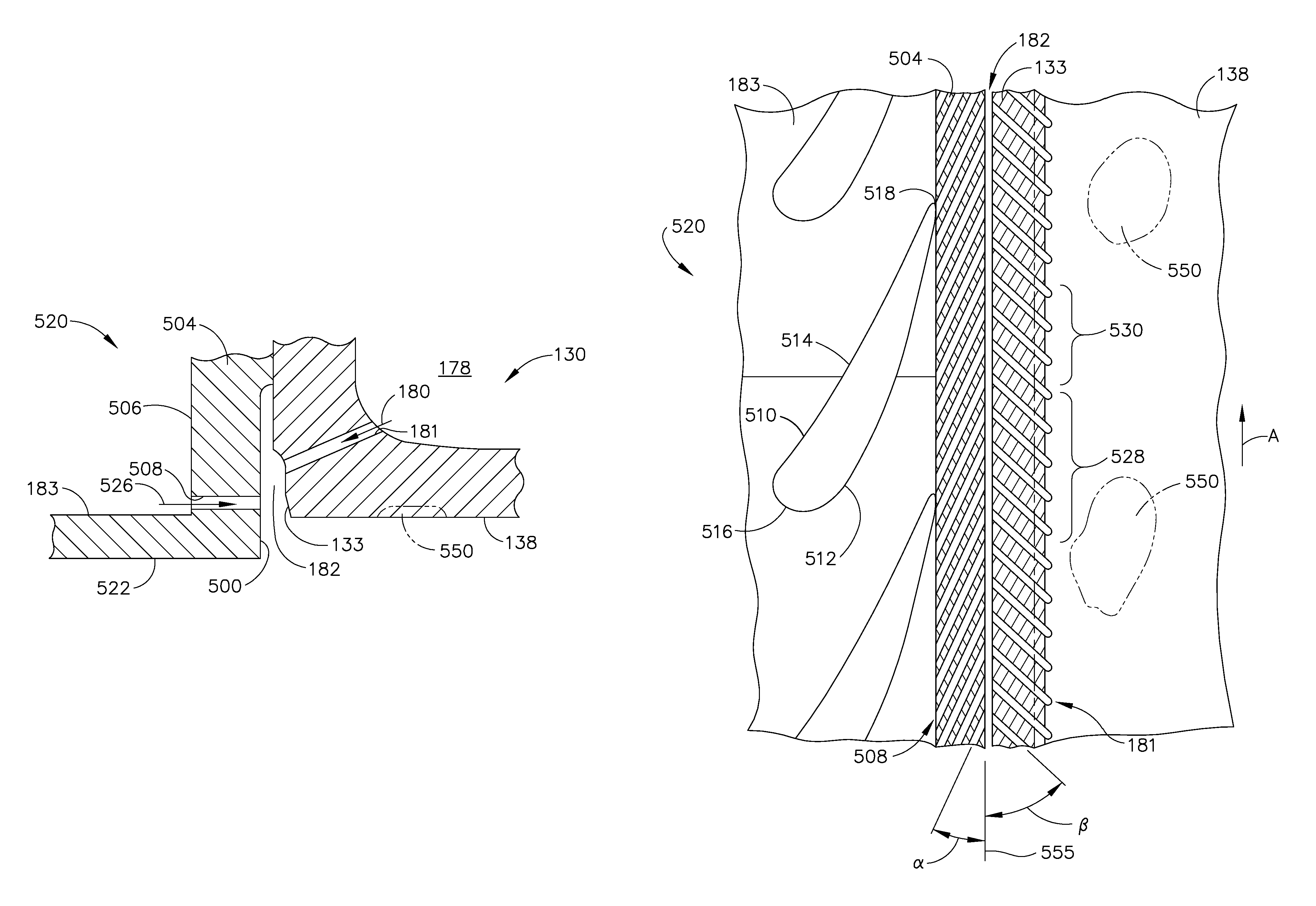
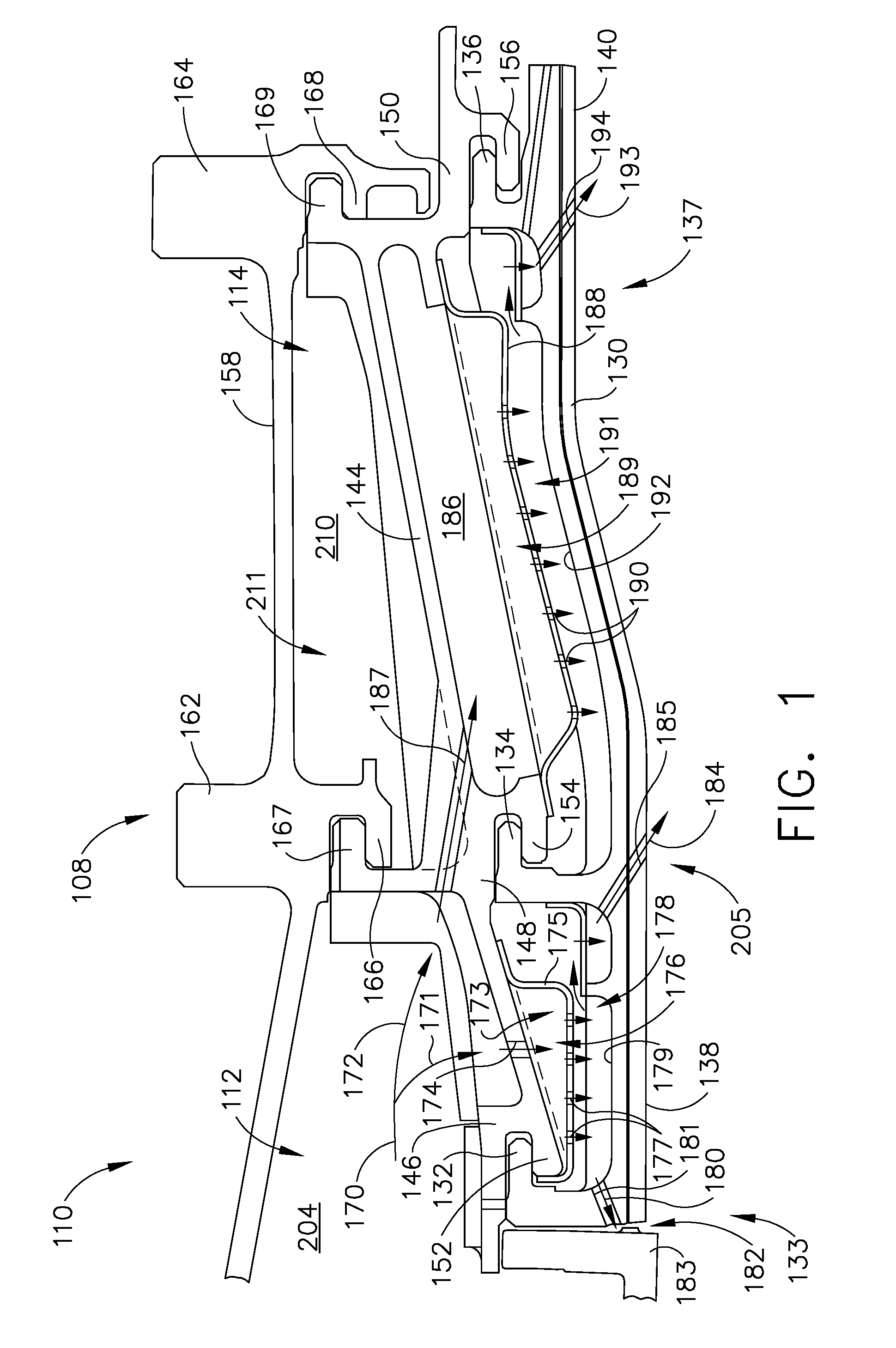
[0017]The present invention provides a turbine shroud cooling system for minimizing hot gas ingestion into a gap defined between a trailing edge of the high pressure turbine nozzle and a leading edge of the adjacent shroud segment. The turbine shroud cooling system facilitates forming a barrier between the hot gas flow path flowing through the high pressure turbine and cooling air flowing through a gap defined between the turbine nozzle and the shroud segment.

[0018]Although the present invention is described below in reference to its application in connection with cooling a shroud assembly of an aircraft gas turbine, it should be apparent to those skilled in the art and guided by the teachings herein provided that with appropriate modification, the cooling system or assembly of the present invention can also be suitable to facilitate cooling other turbine engine components, such as, but not limited to, the nozzle and / or vane sections.

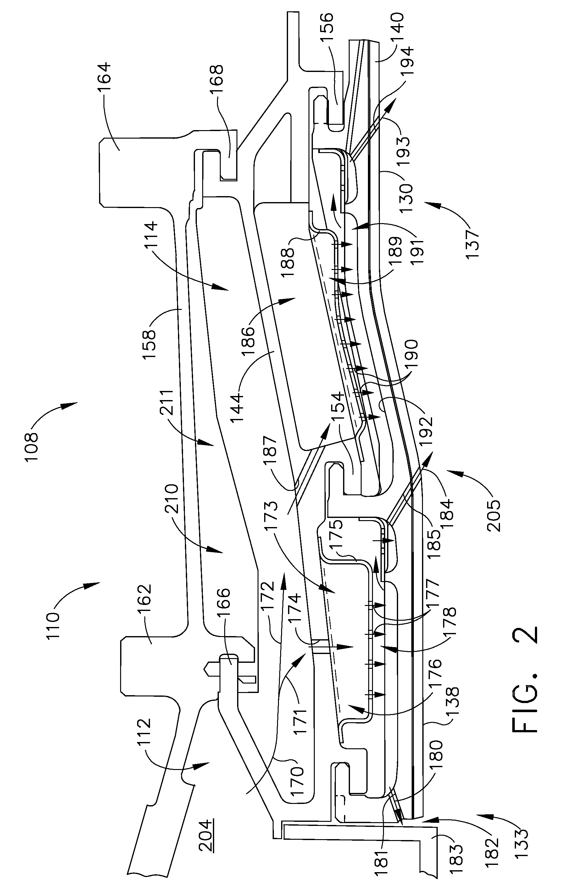
[0019]FIG. 1 is a side view of an exemplary shrou...


PUM

PropertyMeasurementUnit
discharge angleaaaaaaaaaa
areaaaaaaaaaaa
diameteraaaaaaaaaa

Abstract

A method of assembling a gas turbine engine is provided. The method includes coupling at least one turbine nozzle segment within the gas turbine engine. The at least one turbine nozzle segment includes at least one airfoil vane extending between an inner band and an outer band that includes an aft flange and a radial inner surface. The method also includes coupling at least one turbine shroud segment downstream from the at least one turbine nozzle segment, wherein the at least one turbine shroud segment includes a leading edge and a radial inner surface, coupling a cooling fluid source in flow communication with the at least one turbine nozzle segment such that cooling fluid channeled to each turbine nozzle outer band aft flange is directed at an oblique discharge angle towards the leading edge of the at least one turbine shroud segment, and channeling the cooling fluid through at least a first group of cooling openings having a larger aggregate cross-sectional area and a second group of cooling openings having a smaller aggregate cross-sectional area to facilitate preferential cooling of the turbine shroud.

Description

STATEMENT REGARDING FEDERALLY SPONSORED RESEARCH & DEVELOPMENT[0001]The U.S. Government may have certain rights in this invention pursuant to contract number N00019-04-C-0093.BACKGROUND OF THE INVENTION[0002]This invention relates generally to gas turbine engines and, more particularly, to methods and systems for cooling integral turbine nozzle and shroud assemblies.[0003]One known approach to increase the efficiency of gas turbine engines requires raising the turbine operating temperature. However, as operating temperatures are increased, the thermal limits of certain engine components may be exceeded, resulting in reduced service life and / or material failure. Moreover, the increased thermal expansion and contraction of components may adversely affect component clearances and / or component interfitting relationships. Consequently, conventional cooling systems have been incorporated into gas turbine engines to facilitate cooling such components to avoid potentially damaging consequen...

Claims


Application Information

Patent Timeline
Patent Type & Authority Patents(United States)
IPC IPC(8): F01D25/12
CPCF01D9/04F01D11/08Y02T50/671Y02T50/676Y10T29/49346F05D2240/81Y10T29/53443F05D2240/11Y02T50/60
Inventor LEE, CHING-PANGESTILL, ERIC ALANLAFLEN, JAMES HARVEYVITT, PAUL HADLEYWYMORE, MICHAEL ELLIOT
Owner GENERAL ELECTRIC CO
Why Eureka
Try Eureka