
Fuel cell manufacturing method and fuel cell

a fuel cell and manufacturing method technology, applied in the field of fuel cells, can solve the problems of reducing the performance of the resulting fuel cell, affecting the production efficiency of the fuel cell, so as to prevent a potential short circuit

Inactive Publication Date: 2009-11-03
TOYOTA JIDOSHA KK
View PDF27 Cites 68 Cited by
  • Summary
  • Abstract
  • Description
  • Claims
  • Application Information

AI Technical Summary

Benefits of technology

The present invention provides a manufacturing method for a fuel cell that prevents potential short circuits and improves performance. The method includes forming a hydrogen-permeable metal layer and an electrolyte layer with proton conductivity on the metal layer, and a conductive layer that blocks off an electrical connection between the conductive layer and the metal layer via pores in the electrolyte layer. The conductive layer can be a separate layer or a part of the electrolyte layer. The method also includes releasing a conductive material towards the electrolyte layer at a specific angle to prevent the conductive material from being deposited on the hydrogen-permeable metal layer. The invention addresses the issue of pore-related short circuits and ensures a reliable fuel cell performance.

Problems solved by technology

There are, however, great difficulties in forming a sufficiently thin and dense film of the solid electrolyte layer, and it is highly probable that pores in the form of micro-cracks or pinholes are present in the solid electrolyte layer.
Such invasion of the electrically conductive material into the pores may cause a short circuit between the conductive layer and the hydrogen-permeable metal layer and lower the performance of the resulting fuel cell.

Method used


Image

  • Fuel cell manufacturing method and fuel cell
  • Fuel cell manufacturing method and fuel cell
  • Fuel cell manufacturing method and fuel cell

Examples


first embodiment

A. Structure of Fuel Cell

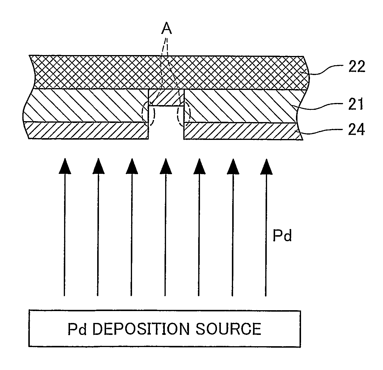
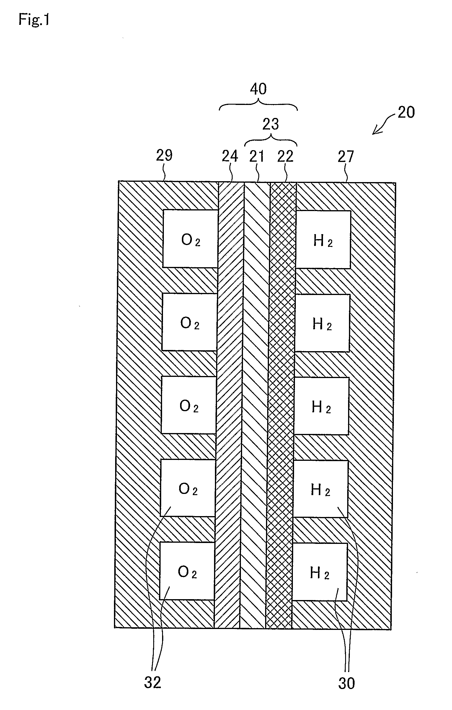
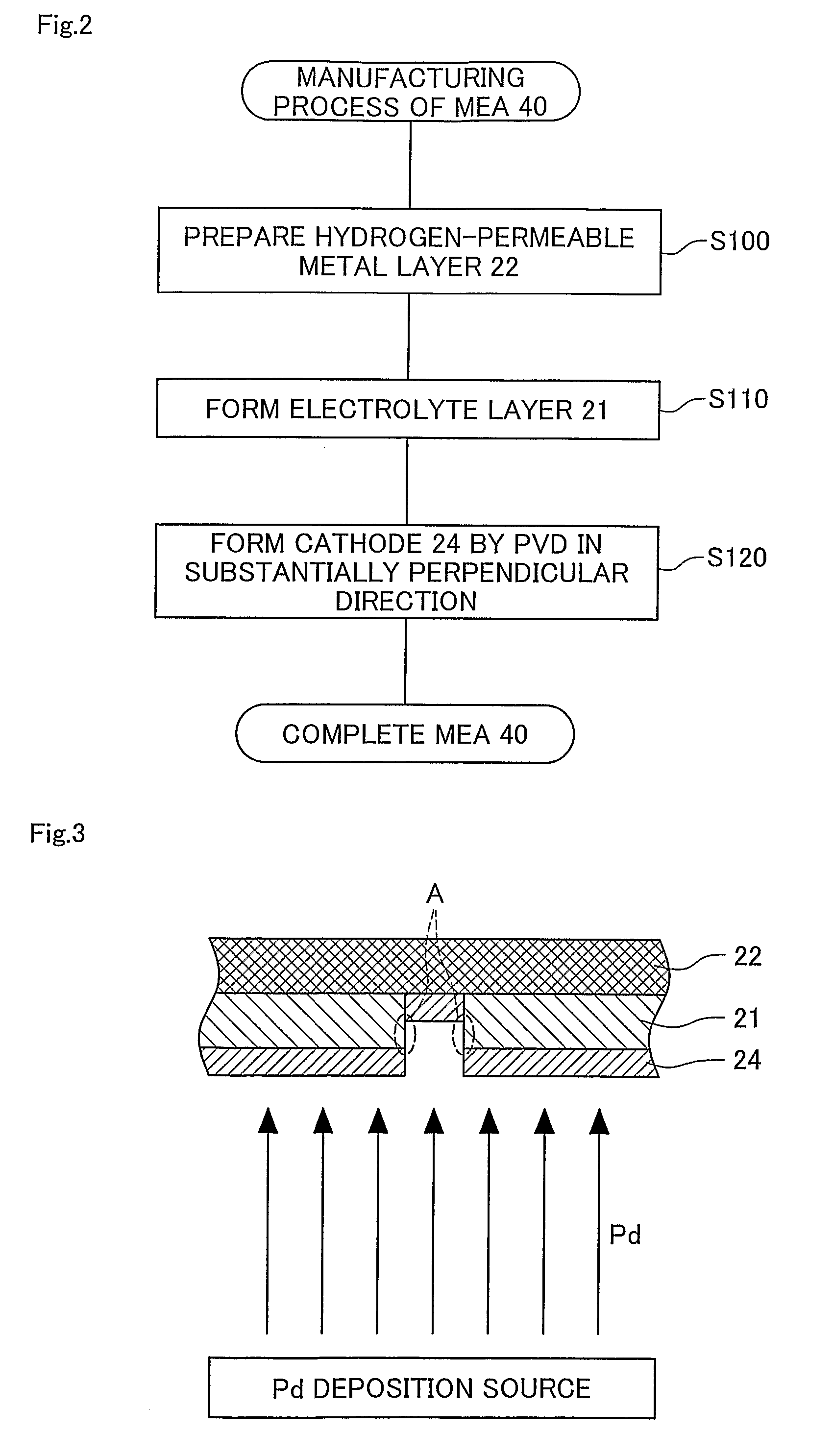
[0052]FIG. 1 is a sectional view schematically illustrating the structure of a unit fuel cell 20 as a unit of fuel cells in one embodiment of the invention. The unit fuel cell 20 has an electrolyte module 23 including a hydrogen-permeable metal layer 22 and an electrolyte layer 21, a cathode 24 formed on the electrolyte layer 21, and a pair of gas separators 27 and 29. An in-cell fuel gas conduit 30 is defined by and formed between the gas separator 27 and the hydrogen-permeable metal layer 22 to allow passage of a hydrogen-containing fuel gas. Similarly an in-cell oxidizing gas conduit 32 is defined by and formed between the gas separator 29 and the cathode 24 to allow passage of an oxygen-containing oxidizing gas. The integral body of the hydrogen-permeable metal layer 22, the electrolyte layer 21, and the cathode 24 forms an MEA (membrane electrode assembly) 40. The actually used fuel cells have a stack structure including a number of the unit fuel cells ...

second embodiment

[0066]FIG. 4 schematically shows an essential part of a manufacturing process of the MEA 40 of the fuel cell in a second embodiment of the invention. The manufacturing process of the second embodiment has a difference only in formation of the cathode 24 from the manufacturing process of the first embodiment shown in the flowchart of FIG. 2. FIG. 4 shows formation of the cathode 24 in the second embodiment. Like the first embodiment, the procedure of the second embodiment activates an electrode material release source that releases an electrode material like Pd in one fixed direction and thereby deposits the electrode material onto the electrolyte layer 21 to form the cathode 24. As shown in FIG. 4, the cathode formation step of the second embodiment corresponding to step S120 in the flowchart of FIG. 2 releases the electrode material from the electrode material release source at a specific angle to prevent the electrode material from being deposited on the surface of the hydrogen-pe...

third embodiment

[0069]FIG. 5 is a sectional view illustrating essential part of an MEA 140 in a third embodiment of the invention. The MEA 140 replaces the MEA 40 in the fuel cell of the first embodiment. In the embodiments described below, the like elements to those of the MEA 40 are expressed by the like numerals. The manufacturing process of the MEA 140 forms the electrolyte module 23 in the same manner as steps S100 and S110 in the flowchart of FIG. 2 and fills the pores of the electrolyte layer 21 with dielectric particles 42, prior to formation of the cathode 24. The manufacturing process then forms the cathode 24 to cover the electrolyte layer 21 having the pores filled with the dielectric particles 42.

[0070]The dielectric particles 42 packed into the pores of the electrolyte layer 21 are, for example, aluminum oxide (alumina) particles or silicon dioxide (silica) particles. The dielectric particles 42 are required to have a smaller particle diameter than the width of the pores present in th...


PUM

PropertyMeasurementUnit
operating temperatureaaaaaaaaaa
thicknessaaaaaaaaaa
thicknessaaaaaaaaaa

Abstract

The manufacturing method of the invention is applied to manufacture a unit fuel cell 20, which has a hydrogen-permeable metal layer 22 of a hydrogen-permeable metal and an electrolyte layer 21 that is located on the hydrogen-permeable metal layer 22 and has proton conductivity. The method first forms the electrolyte layer 21 on the hydrogen-permeable metal layer 22, and subsequently forms an electrically conductive cathode 24 on the electrolyte layer 21 to block off an electrical connection between the cathode 24 and the hydrogen-permeable metal layer 22. The method releases Pd toward the electrolyte layer 21 in a direction substantially perpendicular to the electrolyte layer 21 to form a Pd layer as the cathode 24 that is thinner than the electrolyte layer 21. This arrangement of the invention effective prevents a potential short circuit, for example, between the cathode and the hydrogen-permeable metal layer, in the fuel cell, due to pores present in the electrolyte layer.

Description

TECHNICAL FIELD[0001]The present invention relates to a fuel cell and more specifically pertains to a fuel cell including an electrolyte layer and a hydrogen-permeable metal layer.BACKGROUND ART[0002]Among diversity of proposed fuel cells, there is a known fuel cell having a hydrogen-permeable palladium metal film that is formed on a proton-conductive electrolyte layer and functions as an anode. The fuel cell of this structure is manufactured by, for example, forming a film of a solid electrolyte layer, such as a ceramic layer, on a thin film of a hydrogen-permeable metal layer.[0003]There are, however, great difficulties in forming a sufficiently thin and dense film of the solid electrolyte layer, and it is highly probable that pores in the form of micro-cracks or pinholes are present in the solid electrolyte layer. In the process of forming an electrolyte layer on a hydrogen-permeable metal layer and subsequently forming a conductive layer, such as an electrode, on the electrolyte...

Claims


Application Information

Patent Timeline
Patent Type & Authority Patents(United States)
IPC IPC(8): H01M4/86B05D5/12H01M4/00H01M4/02H01M4/88H01M4/94H01M8/02H01M8/04H01M8/10H01M8/12
CPCH01M4/881H01M4/8817H01M4/8867H01M8/04216H01M8/1004H01M4/94Y02E60/521H01M2300/0091Y02P70/50Y02E60/50
Inventor AOYAMA, SATOSHIITO, NAOKISATO, HIROMICHI
Owner TOYOTA JIDOSHA KK
Features
  • Generate Ideas
  • Intellectual Property
  • Life Sciences
  • Materials
  • Tech Scout
  • Unparalleled Data Quality
  • Higher Quality Content
  • 60% Fewer Hallucinations
Learn More