Ultrasonic sensor

a technology of ultrasonic sensor and vibration member, which is applied in the field of ultrasonic sensor, can solve the problems of difficult balance and difficult resonance of ultrasonic detection element, and achieve the effect of improving the detection sensitivity of ultrasonic sensor to ultrasonic wave, reducing the size of the acoustic matching layer, and increasing the vibration amplitude of the vibration member

Active Publication Date: 2009-11-03
DENSO CORP
View PDF5 Cites 17 Cited by
  • Summary
  • Abstract
  • Description
  • Claims
  • Application Information

AI Technical Summary

Benefits of technology

[0007]According to the above ultrasonic sensor, the vibration member of the ultrasonic detection element resonates with the repeat deformation of the acoustic matching layer. The repeat deformation is caused by the standing wave in the acoustic matching layer, the standing wave which is generated by the ultrasonic wave received by the first surface of the acoustic matching layer. Thus the configuration increases the vibration amplitude of the vibration member and thus the detection sensitivity of the ultrasonic sensor to the ultrasonic wave is improved. Here the increase of the vibration amplitude is independent from the area of the first surface of the acoustic matching layer. Therefore the downsizing of the acoustic matching layer is realized, and the ultrasonic sensor having improved detection sensitivity to the ultrasonic wave is realized.

Problems solved by technology

When bulky piezoelectric material is used for the ultrasonic detection element, it is difficult for the ultrasonic detection element to resonate with the vibration of the acoustic matching layer with increasing the reception sensitivity and improving the detection sensitivity to the ultrasonic wave.
The problem is that it has been difficult to balance two goals for the downsizing of the acoustic matching layer and the improving of the detection sensitivity to the ultrasonic wave.

Method used


Image

  • Ultrasonic sensor
  • Ultrasonic sensor
  • Ultrasonic sensor

Examples


first embodiment

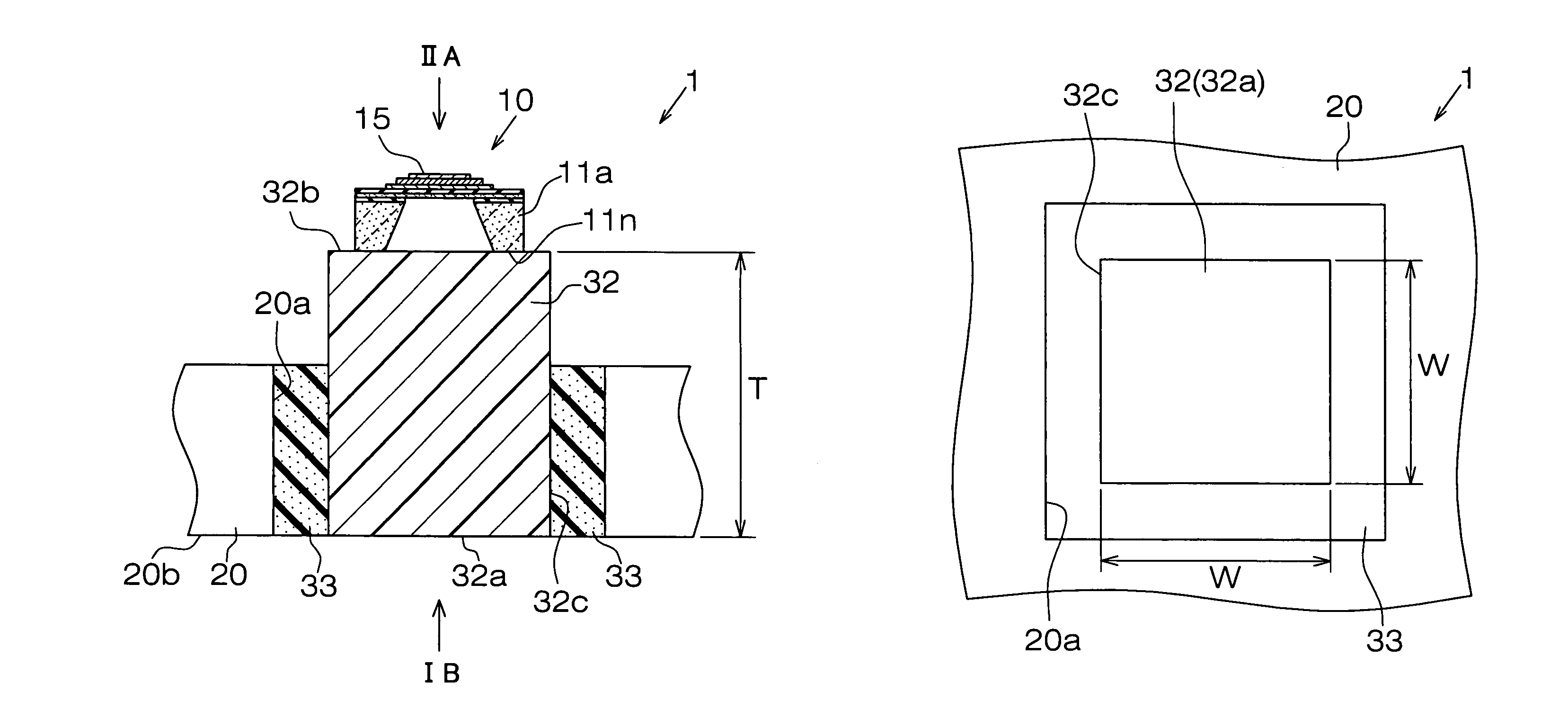
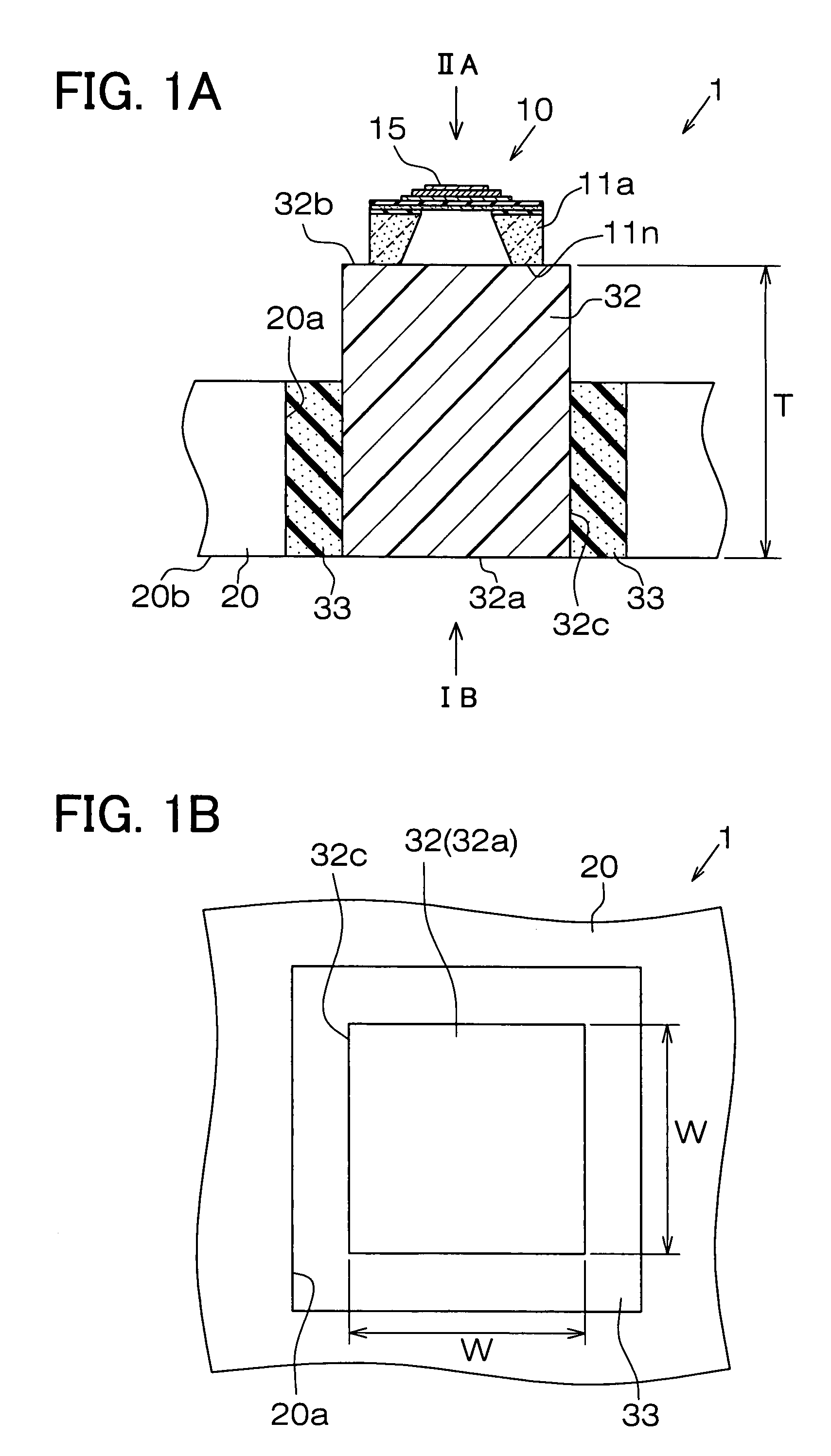
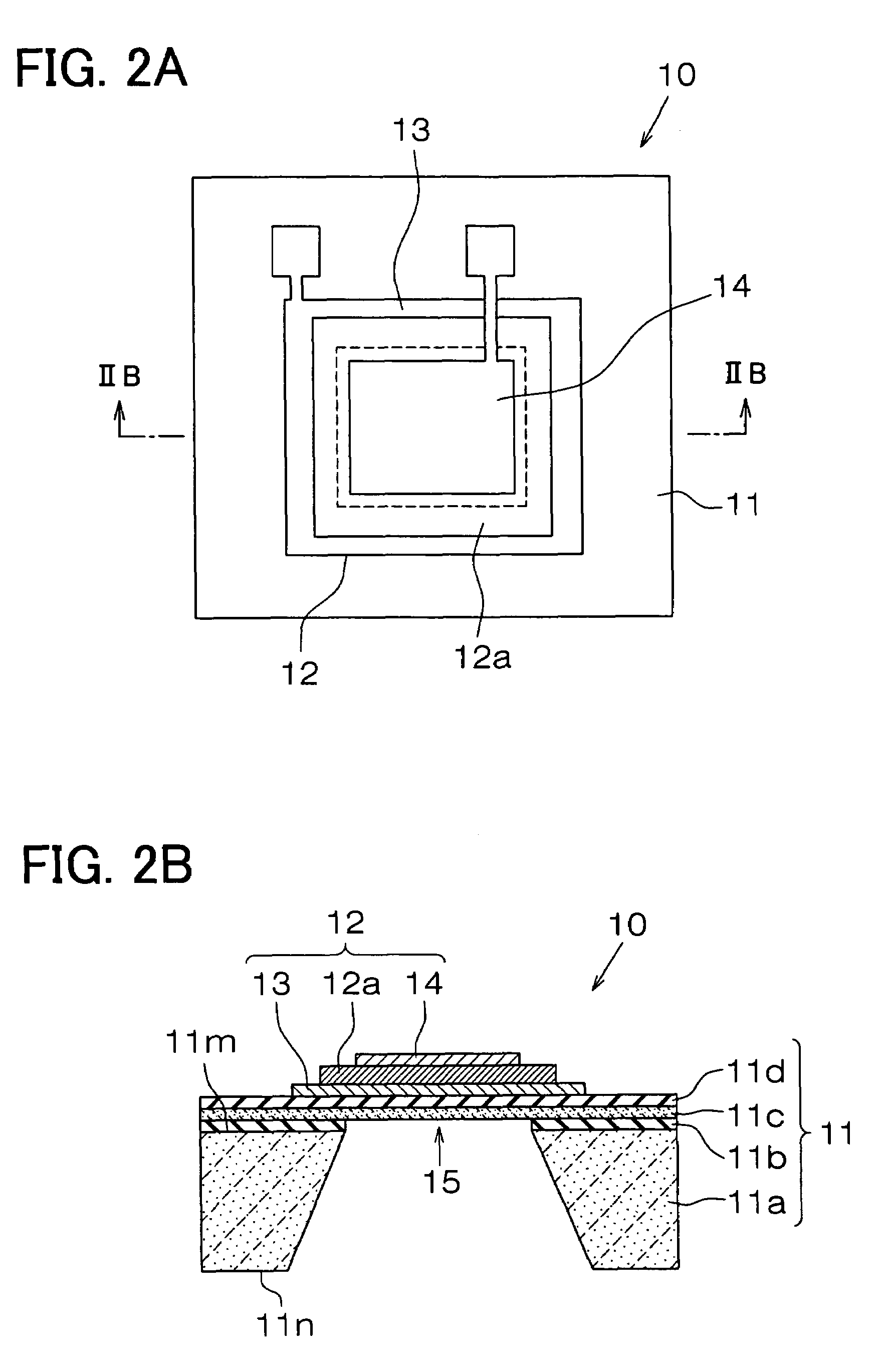
[0021]An ultrasonic sensor shown hereafter is a form of an obstacle sensor mounted to a vehicle, which is an example of the uses of the ultrasonic sensor. FIGS. 1A and 1B show schematic views of an ultrasonic sensor according to a first embodiment. FIG. 1A shows a vertical cross-sectional view of the ultrasonic sensor. FIG. 1B shows a plan view of the ultrasonic sensor where the view is taken from the side of an acoustic matching layer (cf. an arrow IB in FIG. 1A). FIGS. 2A and 2B show a schematic view of an ultrasonic detection element 10. The view direction of FIG. 2A corresponds to an arrow IIA in FIG. 1A. The view of FIG. 2B is a cross sectional view taken along line IIB-IIB in FIG. 2A. FIGS. 3A and 3B are conceptual diagram of a deformation of the acoustic matching layer 32 due to a standing wave. FIG. 4 shows example places for mounting the ultrasonic sensor to the vehicle. The direction from the vehicle internal to the vehicle external is expressed as the arrow IIA in FIG. 1A...

second embodiment

[0050]FIGS. 5A and 5B are schematic views of a part of an ultrasonic sensor 2 according to the second embodiment. FIG. 5A shows a plain view of the ultrasonic sensor 2 where the view is taken from the vehicle internal. FIG. 5B is a cross sectional view of the ultrasonic sensor 2 where the view is taken along line VB-VB in FIG. 5A. FIG. 6 is a diagram for explaining a modification example according to the second embodiment.

[0051]The ultrasonic sensor 2 according to the second embodiment includes an ultrasonic detection element 80 whose vibration member 85 is cantilevered. As shown in FIGS. 5A and 5B, the vibration member 85 of the ultrasonic detection element 80 is multilayered. Each layer is disposed in following order: a silicon active layer 11c, a second insulating film 11d and a piezoelectric vibration detection element 82. In the piezoelectric vibration detection element 82, a piezoelectric film 82A is disposed between a bottom electrode 83 and a top electrode 84. The multilayer...

third embodiment

[0055]FIG. 7 shows an ultrasonic sensor 3 according to a third embodiment. For an ultrasonic detection element, the ultrasonic sensor 3 has an ultrasonic detection element 40, which includes a capacitor type vibration detection element 41. As shown in FIG. 7, the capacitor type vibration detection element 41 includes a first electrode 16 and a second electrode 17, which are facing each other. A capacitance change between the electrodes results in the detection of the ultrasonic wave. The first electrode 16 is formed on a first insulating film 11b. The second electrode 17 is disposed in a way that the two electrodes (16,17) have a given space between the first and second electrodes (16,17). Here, the central parts of the support 11a and the first insulating film 11b are not removed, and thereby, the support 11a and the first insulating film 11b have a flat plate shape.

[0056]The first electrode 16 is configured to be an appropriate shape (i.e., thickness and width etc.) in order to re...


PUM


Abstract

An ultrasonic sensor for detecting an ultrasonic wave, which is output from an ultrasonic generator and reflected by an object to be detected, the ultrasonic sensor includes: an acoustic matching layer having a first surface and a second surface, the first surface which receives the ultrasonic wave, and the second surface which is opposite to the first surface; and an ultrasonic detection element including a vibration member. The vibration member is coupled with the second surface of the acoustic matching layer. The acoustic matching layer is repeatedly deformable in accordance with a standing wave, which is generated in the acoustic matching layer by the received ultrasonic wave. The vibration member resonates with the repeat deformation of the acoustic matching layer.

Description

CROSS REFERENCE TO RELATED APPLICATION[0001]This application is based on Japanese Patent Application No. 2006-260737 filed on Sep. 26, 2006, the disclosure of which is incorporated herein by reference.FIELD OF THE INVENTION[0002]The present invention relates to an ultrasonic sensor.BACKGROUND OF THE INVENTION[0003]A conventional ultrasonic sensor includes an ultrasonic transducer disposed on a substrate made from material such as metal and resin. The ultrasonic sensor is mounted to, for example, a vehicle. The ultrasonic sensor sends an ultrasonic wave to an object and receives the ultrasonic wave reflected by the object. The sending and receiving of the ultrasonic wave is done by an element capable of sending and receiving the ultrasonic wave. The wave sent and received provides information on an object around the vehicle, such as a location of the object, a distance from the object, a two-dimensional shape of the object and a three dimensional shape of the object.[0004]Some of the...

Claims


Application Information

Patent Timeline
Patent Type & Authority Patents(United States)
IPC IPC(8): H01L41/08H01L41/053
CPCB06B1/0648G10K11/004G01S7/521
Inventor SUGIURA, MAKIKOWATANABE, KAZUAKIOKUDA, YASUYUKI
Owner DENSO CORP
Why Eureka
Try Eureka