Blow molded container

a container and blow molding technology, applied in the field of blow molding containers, can solve the problems of cracking in the container, insufficient sealing strength between the rib strips, and insufficient sealing strength, etc., and achieve the effects of increasing the area of pressure bonding, enhancing pressing strength, and increasing the resistance to shearing for

Active Publication Date: 2009-11-10
YOSHINO KOGYOSHO CO LTD
View PDF5 Cites 23 Cited by
  • Summary
  • Abstract
  • Description
  • Claims
  • Application Information

AI Technical Summary

Benefits of technology

[0035]This invention having the above-described configuration has the following effects:
[0036]In the invention of claim 1, the contact faces formed by the outer layers and the combined inner layer in the bottom rib twist and turn in the presence of cavities. This meandering shape results in an increased area of pressure bonding and in the enhanced pressing strength. In addition, it increases resistance to the shearing force that works in the direction parallel to the main part of the pressure-bonded portions.
[0037]Undercut engagement portions in a sigmoid shape are formed in the direction against the peel-off of rib strips by the contact faces of the portions of both rib strips at positions facing the expanded portions. Since this engagement serves as an undercut formed in the direction against the peel-off of both rib strips, it prevents both rib strips substantially from being peeled from each other, and thus, strongly prevents the occurrence of bottom cracking.
[0038]In the invention of claim 2, the undercut engagement portions have a large extent of engagement, which further strengthens the extent of crack prevention.
[0039]In the invention of claim 3, the pushing force of blow mold pins acts on the pressure-bonded portions at the rear of cavities effectively, strongly, and reliably as the pressure bonding force. Therefore, these pressure-bonded portions have quite high pressing strength for the outer / inner layers, and can provide a bottom having stable mechanical strength with no bottom cracking.
[0040]Since the pressure-bonded portion at the rear of each cavity is sufficiently thin, it is hardly affected by shrinkage when the bottom seal is cooled and hardened. Even if shrink-deforming force is applied from surroundings, this deforming force is absorbed as deflective deformation of the entire pressure-bonded portion, thus preventing the peel-off from occurring in the pressure-bonded portion.

Problems solved by technology

However, anti-peeling strength between the pair of rib strips 14 is not always sufficient, and thus there is a strong need for further enhanced anti-peeling strength between the pair of rib strips 14 in the bottom seal 13.
As a result, there arises a problem that the pair of rib strips 14 in the bottom seal 13 breaks away from each other, thus creating a crack in the container 1.

Method used


Image

  • Blow molded container
  • Blow molded container
  • Blow molded container

Examples


Embodiment Construction

[0072]This invention is further described with respect to a preferred embodiment, now referring to the drawings.

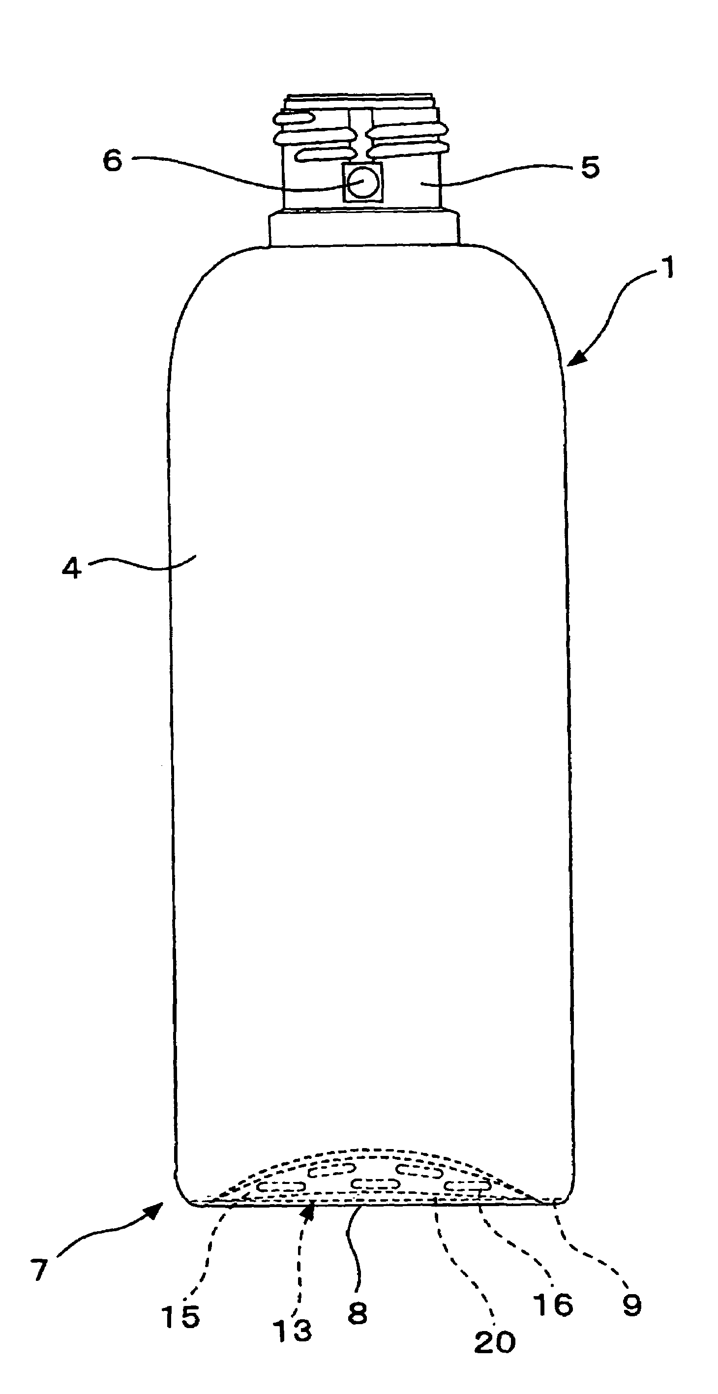
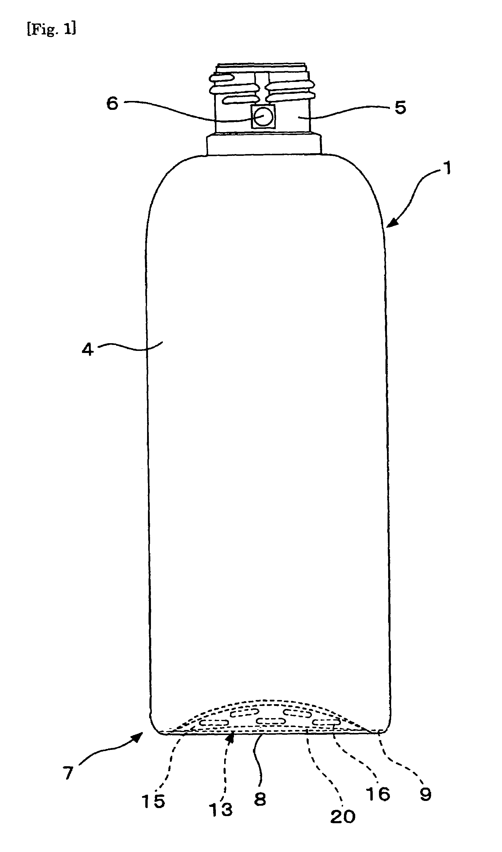
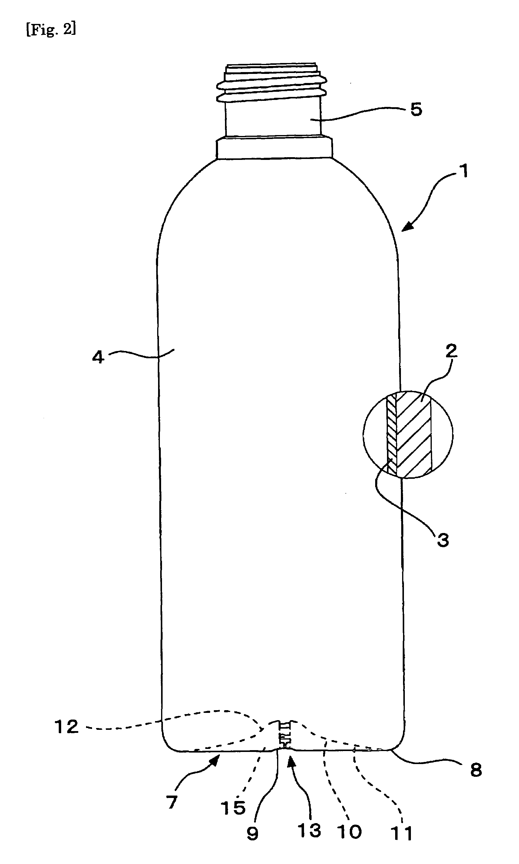
[0073]FIG. 1 is a front elevational view of the container 1 according to this invention. FIGS. 2 and 3 are a side view and a bottom view, respectively, of the same. The container 1 is a blow molded container in which outer layer 2 is laminated with inner layer 3 (See FIG. 2). The outer layer 2 is made of a synthetic resin material, such as polyethylene, polypropylene, and the like, and is molded so as to have a necessary ability to retain the shape of its own. The inner layer 3 is made of a synthetic resin material that is little compatible with the outer layer 2, such as nylon, ethylene vinyl alcohol copolymer, polyethylene terephthalate, and the like, and is molded into a bag capable of flexible deformation.

[0074]This container 1 comprises a cylindrical body 4; a neck 5 standing on the upper end of the body 4, with screw thread notched on the outer surface, and having ai...


PUM

PropertyMeasurementUnit
thicknessaaaaaaaaaa
widthaaaaaaaaaa
heightaaaaaaaaaa

Abstract

The invention is aimed at preventing bottom crack from occurring in a peelably laminated plastic container and maintaining the container stably in good in-use condition. This can be achieved by increasing the anti-peeling strength of a pair of rib strips, with which the bottom rib is formed, in the bottom seal that has been obtained by pinching off the parison at the bottom and molding the parison into a blow molded, peelably laminated plastic container.The bottom seal 13 of a blow molded, peelably laminated container 1 is reinforced by a pair of rib strips 14 which are pressed to each other to form the bottom rib 15. A multiple number of cavities 16 are formed in the bottom rib 15 in such a way that the rib strip 14 on one side is pushed toward, and caved into, the rib strip on the other side at several points, and vice verse. An expanded portion 18 is formed in the ceiling of each cavity 16. As a result, an undercut engagement portion 19 is formed along the contact faces of both rib strips 14 so that anti-cracking bottom strength of the bottom seal is enhanced.

Description

TECHNICAL FIELD[0001]This invention relates to a structure of the seal in the bottom of a blow molded, peelably laminated plastic container.BACKGROUND ART[0002]Peelably laminated containers are known. These containers are blow molded bottles, generally known as delaminatable bottles, and are obtained by laminating a highly shape-retainable outer layer with an inner layer in the shape of a highly flexible bag in an easily peelable manner.[0003]These blow molded, peelably laminated plastic containers are manufactured by extruding together an outer layer and an inner layer having little compatibility with each other to form a laminated parison, and by blow molding this laminated parison. The bottom seal of the container is obtained by pressing the parison flat and pinching off the tube by means of the pinch-off section of a blow mold. However, since the bottom seal basically has a laminated structure of outer layers and inner layers that have little compatibility with each other, the u...

Claims


Application Information

Patent Timeline
Patent Type & Authority Patents(United States)
IPC IPC(8): B65D90/02
CPCB29B11/14B65D1/0276B65D1/0215B29B2911/14066B29B2911/1408B29B2911/14093B29B2911/14113B29B2911/14166B29B2911/14446B29B2911/145B29C49/04B29C49/22B29K2023/06B29K2023/086B29K2023/12B29K2067/00B29K2077/00B29B2911/14053B29C2949/302B29C2949/3016B29C2949/3008B29C2949/3012B29C2949/3026B29C2949/3042B29C2949/0774B29C2949/0782B29C49/071B29C2949/0715B29C49/42B65D1/02B29L2031/712
Inventor FURUSAWA, MITSUOGOTOU, EIJIONO, MASARUARAI, TSUGIO
Owner YOSHINO KOGYOSHO CO LTD
Why Eureka
Try Eureka