
Artificial joint

a technology of artificial joints and joints, applied in the field of artificial joints, can solve the problems of not being able to achieve the effect of using the known artificial joint, and only very inadequately simulated natural joints

Inactive Publication Date: 2009-11-10
HJS GELENK SYST
View PDF16 Cites 65 Cited by
  • Summary
  • Abstract
  • Description
  • Claims
  • Application Information

AI Technical Summary

Benefits of technology

"The present invention provides an improved artificial joint that can achieve both high mobility and durability or long-term load-bearing capacity at the same time. The joint has a first main articular surface and a second main articular surface that work together mechanically to replace the tibia and talus. The radii of the convex curvatures of the second main articular surface are smaller than the corresponding radii of the first main articular surface. This results in an additional degree of freedom in the angular position of the joint directed forward and a reversal of the contact surface between the two main articular surfaces in the rearward- or downward-directed angular position. The joint can achieve one additional degree of freedom in the angular position of the joint directed toward the front or the rear. The shaping of the main articular surfaces can be designed to implement the desired load-bearing capacity and mobility. The joint can achieve both high mobility and durability or long-term load-bearing capacity at the same time."

Problems solved by technology

In medical practice, however, it has been found that the properties of natural joints can be simulated only very inadequately using the known artificial joint.
In particular, it is not possible using the known artificial joint to achieve the properties of natural joints which are suitable for transmitting high forces under load while at the same time having a high measure of mobility under reduced loads.

Method used


Image

  • Artificial joint
  • Artificial joint
  • Artificial joint

Examples


Embodiment Construction

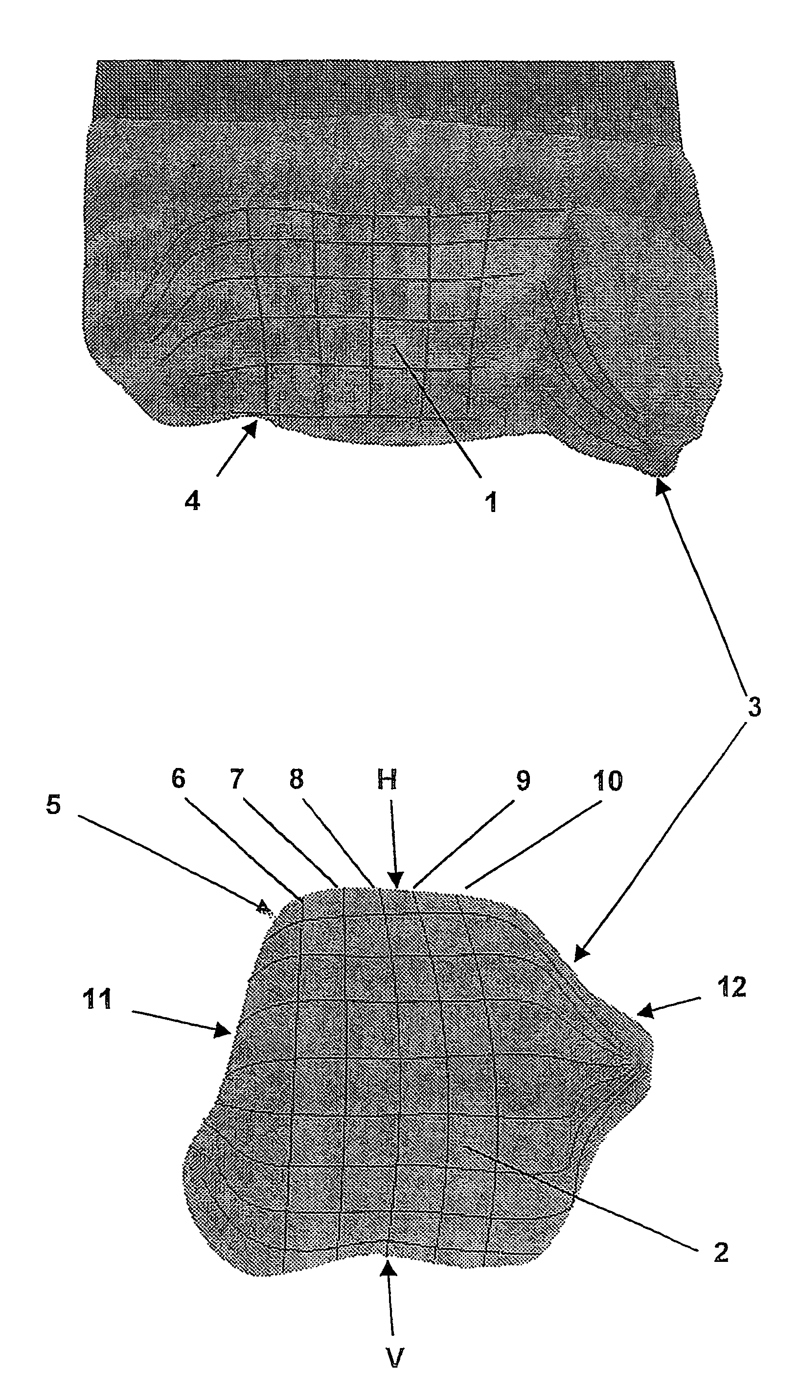
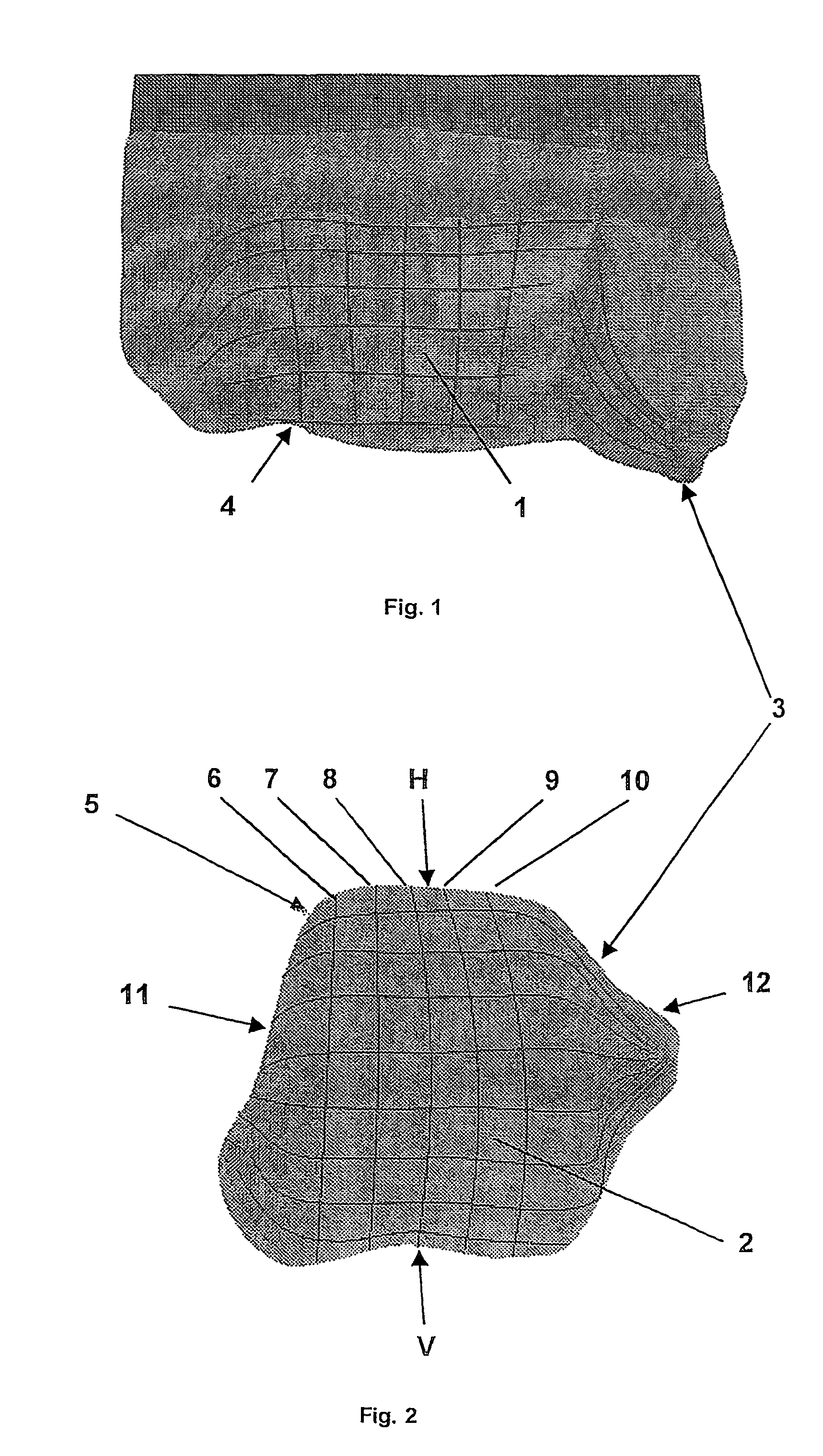
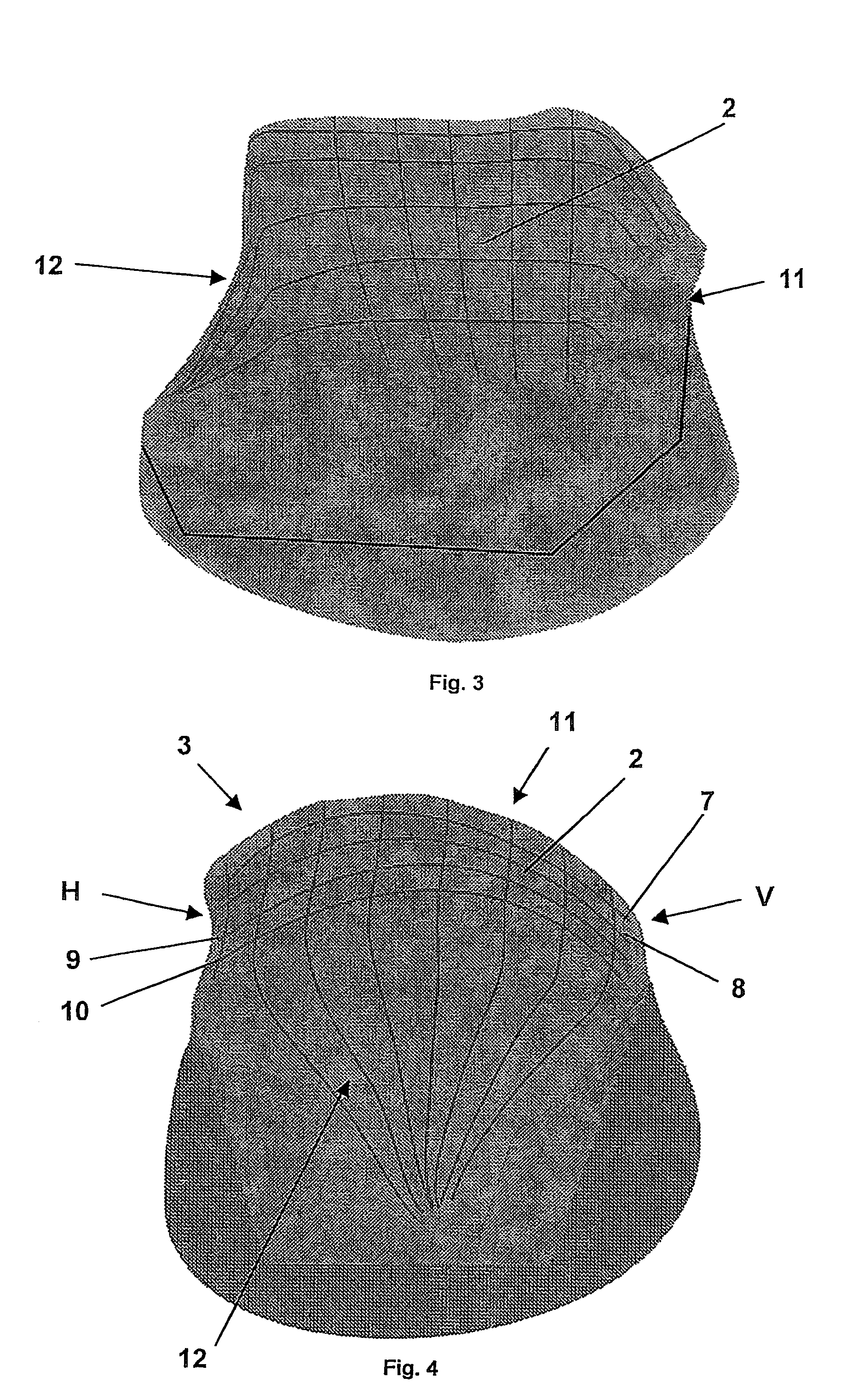
[0028]FIGS. 1 and 2, respectively, show a first main articular surface 1 and a second main articular surface 2 of an artificial joint 3, which is particularly intended for replacement of an ankle joint, the interaction of which is explained in greater detail below with reference to the two figures. The first main articular surface 1 forms a socket 4 due to its largely concave shape and is therefore intended for replacement of the tibia, for example, while a second main articular surface 2 as part of a condyle 5 replacing the talus in particular having a largely convex shape permits mobility with predetermined degrees of freedom. The mobility achieved mainly in this way corresponds to a main function plane of the joint 3. This function plane is perpendicular to the plane of the drawing and corresponds to the sagittal plane. The curvatures 6, 7, 8, 9, 10 of the second main articular surface 2, which are effective here, are labeled in ascending order in the direction from a medial side...


PUM


Abstract

An artificial joint (3), particularly for replacing a talocrural joint, including a first primary joint surface (1) that forms an articular fossa (4) particularly for replacing the tibia composed of concave curvatures extending parallel to a primary function plane of the joint (3), which corresponds to the sagittal plane, and a second primary joint surface (2) which cooperates with the first primary joint surface (1) as a component of a condoyle (5) that replaces the talus and has convex curvatures (7, 8, 9, 10) on the primary function plane that are adapted to the first primary joint surface (1). To achieve high stress resistance and optimal joint mobility, depending on the position of the joint, the radii of the curvatures (7, 8, 9, 10) are calculated such that the differential amounts arising between the corresponding radii of the first and second primary joint surfaces (1, 2) in an ascending angular position (V) relative to a descending angular position and also simultaneously between a medial face (11) and a lateral face (12) of the joint (3) deviate from one another.

Description

CROSS REFERENCE TO RELATED APPLICATIONS[0001]This application is a continuation of international patent application no. PCT / DE03 / 00827, filed Mar. 13, 2003, designating the United States of America, and published in German as WO 03 / 079938 A1 on Oct. 2, 2003, the entire disclosure of which is incorporated herein by reference. Priority is claimed based on Federal Republic of Germany patent application no. DE 102 13 063.9, filed Mar. 22, 2002.BACKGROUND OF THE INVENTION[0002]This invention relates to an artificial joint which is intended in particular for replacement of an ankle joint and has a first main articular surface which forms a joint socket and is intended in particular for replacement of the tibia, composed of concave curvatures parallel to a main function plane of the joint which corresponds to the sagittal plane and with a second main articular surface which is mechanically linked to the first main articular surface as part of a condyle which replaces the talus in particula...

Claims


Application Information

Patent Timeline
Patent Type & Authority Patents(United States)
IPC IPC(8): A61F2/66A61F2/42
CPCA61F2/4202A61F2002/4207A61F2002/4205
Inventor NAEGERL, HANSTHEUSNER, JOACHIMKUBEIN-MEESENBURG, DIETMAR
Owner HJS GELENK SYST
Learn More