Power turbine speed control using electrical load following

a technology of power turbine and load following, which is applied in the direction of electric generator control, rotary clutches, fluid couplings, etc., can solve the problems of reducing the transient handling requirements of any associated energy storage and management system, and it is not desirable to utilise this capability, so as to achieve constant power turbine spool speed

Active Publication Date: 2009-11-10
HAMILTON SUNDSTRAND CORP
View PDF9 Cites 32 Cited by
  • Summary
  • Abstract
  • Description
  • Claims
  • Application Information

AI Technical Summary

Problems solved by technology

Although the two to four second time constant of the aircraft gas turbine engine will never satisfy the near instantaneous load-on and load-off transient capability of electrical systems, obtaining the maximum transient capability from the engine will greatly reduce the transient handling requirements for any associated energy storage and management systems, such as capacitors, batteries, flywheels and so forth.
Furthermore, even if a conventional synchronous generator that can obtain very fast load-on and load-off power transients provides power generation, it may not be desirable to utilise this capability because of the transient response limitations of the engine.

Method used


Image

  • Power turbine speed control using electrical load following
  • Power turbine speed control using electrical load following
  • Power turbine speed control using electrical load following

Examples


Embodiment Construction

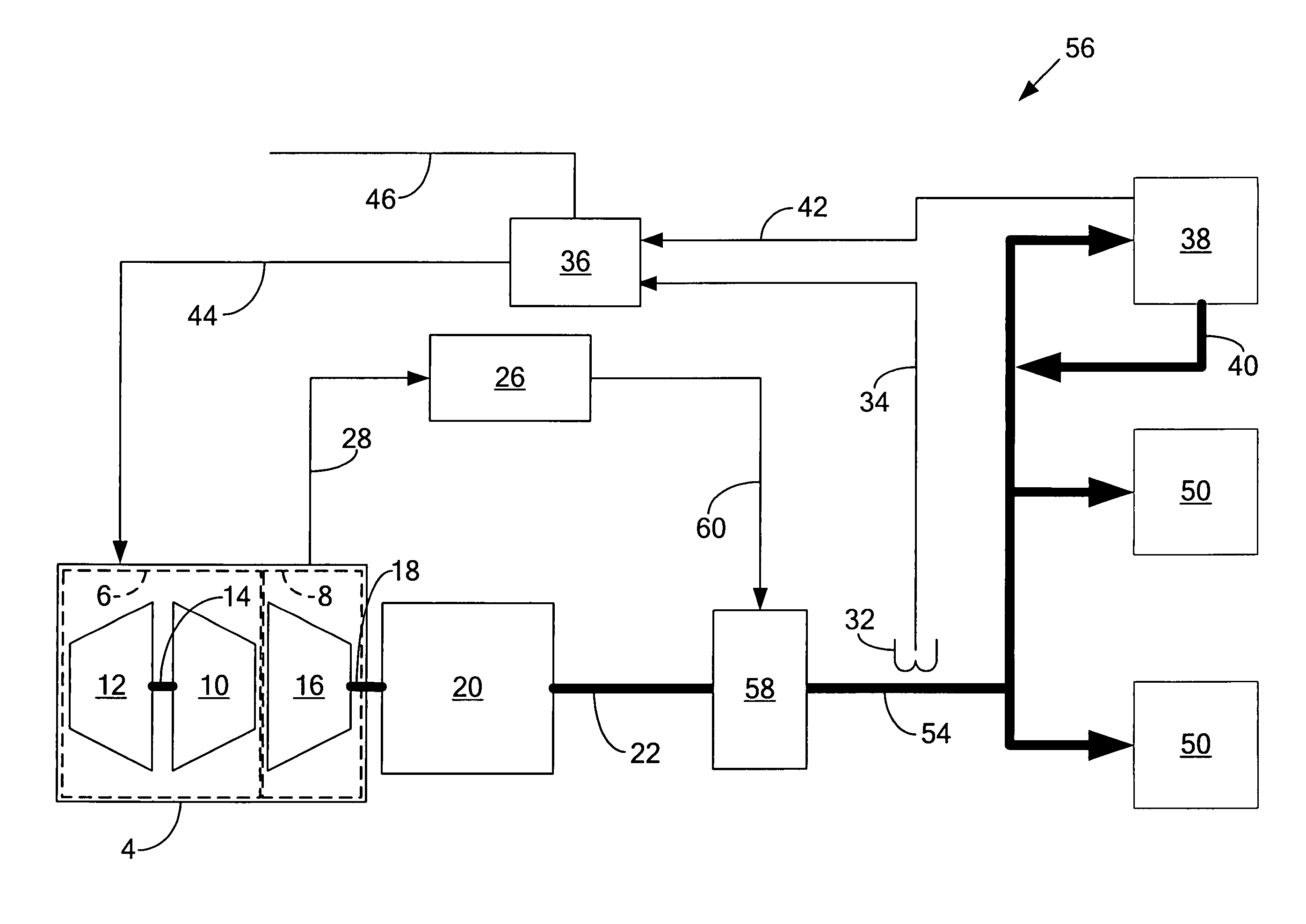
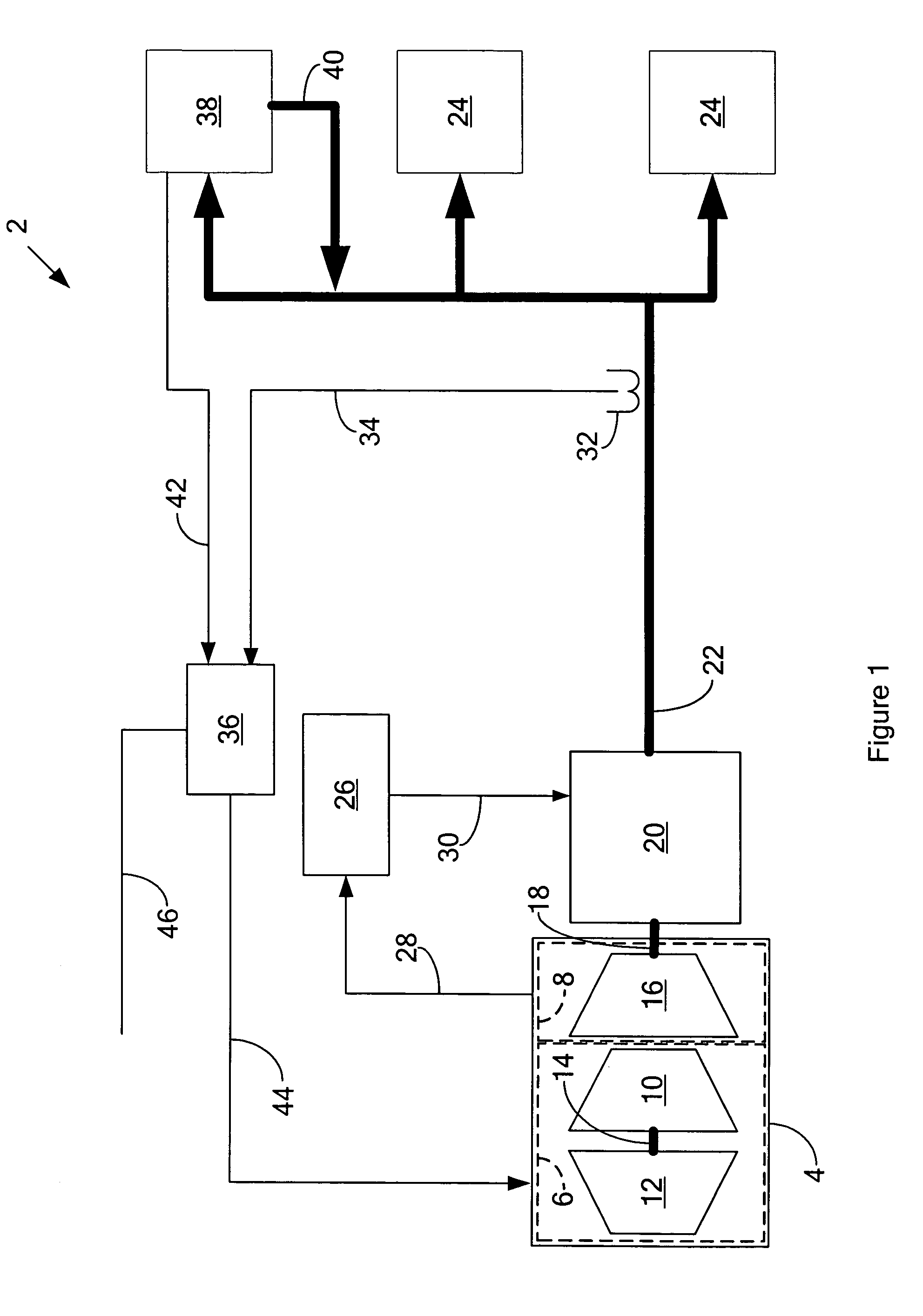
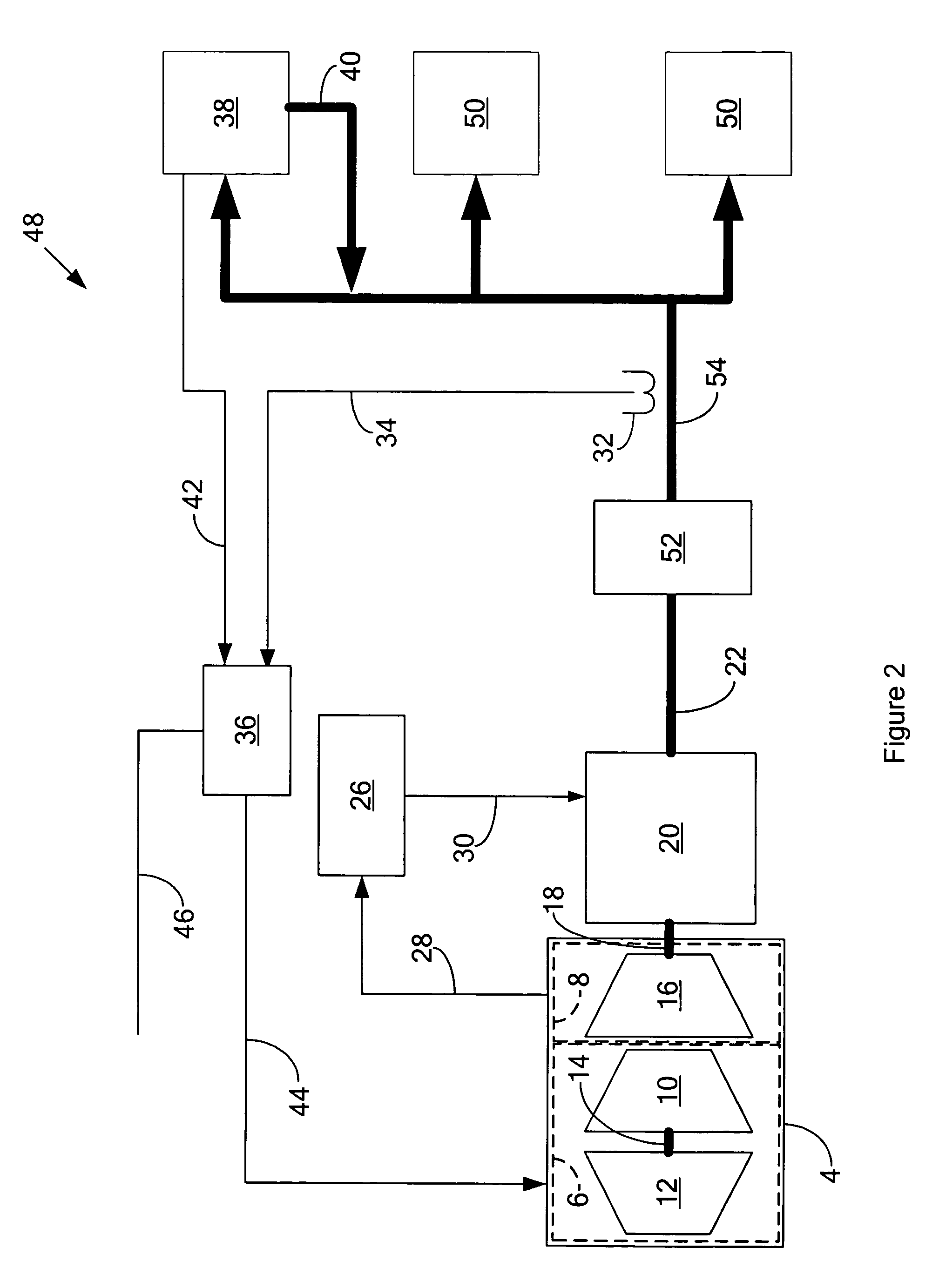
[0010]FIG. 1 is a schematic diagram of a power turbine speed control system 2 for a turboshaft type gas turbine engine 4.according to a first possible embodiment of the invention. The gas turbine engine 4 comprises a gas generator compressor spool 6 and a power turbine spool 8. The gas generator compressor spool 6 comprises a gas generator turbine 10 that drives a gas generator compressor 12 by way of a gas generator shaft 14. The power turbine spool 8 comprises a power turbine 16 that drives a power turbine shaft 18.

[0011]The gas turbine engine 4 drives an electrical generator 20 by way of the power turbine shaft 18. Although the gas generator spool 6 generates combustion gas that imparts torque to the power turbine spool 8, the rotational speed of the power turbine spool 8, and thus rotational speed of the power turbine shaft 18 and the electrical generator 20, is mechanically independent of the rotational speed of the gas generator spool 6.

[0012]The electrical generator 20 is gen...


PUM


Abstract

A power turbine speed control system for a turbo-shaft type gas turbine engine that has a gas generator compressor spool and a power turbine spool and drives an electrical generator that powers at least one electrical load by way of at least one electrical bus, comprises a power turbine controller that senses the rotary speed of the power turbine spool and generates at least one signal that changes the torque of the electrical generator in response to the sensed change in the rotary speed of the power turbine spool.

Description

FIELD OF THE INVENTION[0001]The invention relates to a speed control for a turbo-shaft type gas turbine engine that drives an electrical power generation system, and more particularly to a speed control for a gas turbine engine driven electrical power generation system that maintains a substantially constant engine speed despite changes in electrical loading.BACKGROUND OF THE INVENTION[0002]As aeronautical gas turbine engines of the free turbine turbo-shaft type find expanding applications for power generation applications due to their high achievable power densities, it is becoming increasing important to obtain the maximum transient response capability from the engines. In particular, many of these power generation applications are striving to obtain the most efficient and power dense power generation possible. This efficiency may rely on superconducting generators that have much longer excitation system time constants than the gas turbine engine. Although the two to four second t...

Claims


Application Information

Patent Timeline
Patent Type & Authority Patents(United States)
IPC IPC(8): H02P9/04F02C6/00
CPCF01D15/10F01D21/14F02C3/10F02C6/00F02C9/26F02C9/56F02C9/28F05D2220/76F05D2270/44F05D2270/052F05D2270/304F05D2270/309
Inventor HALSEY, DAVID G.ROMENESKO, CHARLES J.
Owner HAMILTON SUNDSTRAND CORP
Why Eureka
Try Eureka