Non-invasive ultrasonic system to determine internal pressure in flexible tubing

a flexible tubing and non-invasive technology, applied in the field of non-invasive ultrasonic systems to determine internal pressure, can solve the problems of difficult operation and relatively expensive instruments using penetrating energy techniques

Inactive Publication Date: 2009-11-17
MEASUREMENT SPEC
View PDF7 Cites 32 Cited by
  • Summary
  • Abstract
  • Description
  • Claims
  • Application Information

AI Technical Summary

Problems solved by technology

Instruments using a penetrating energy technique ar...

Method used


Image

  • Non-invasive ultrasonic system to determine internal pressure in flexible tubing
  • Non-invasive ultrasonic system to determine internal pressure in flexible tubing
  • Non-invasive ultrasonic system to determine internal pressure in flexible tubing

Examples


Embodiment Construction

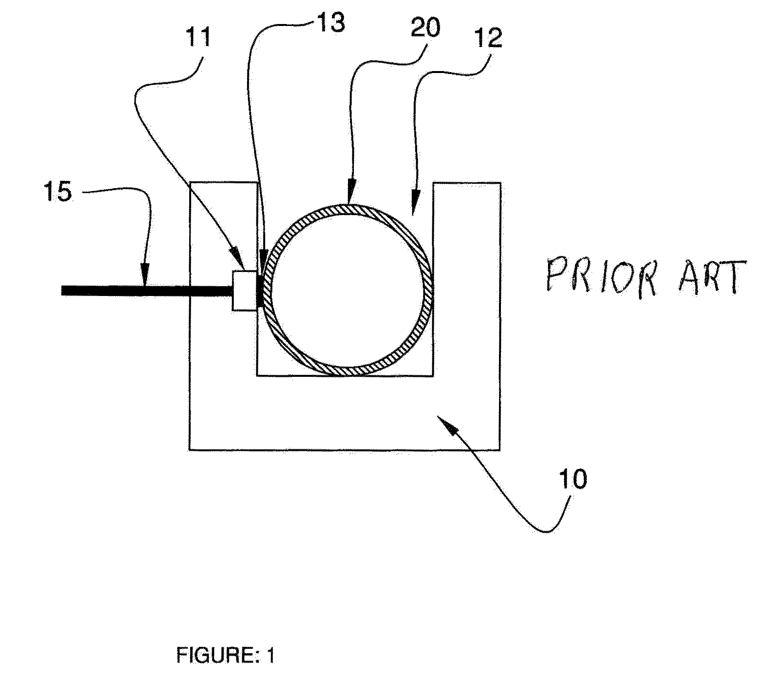
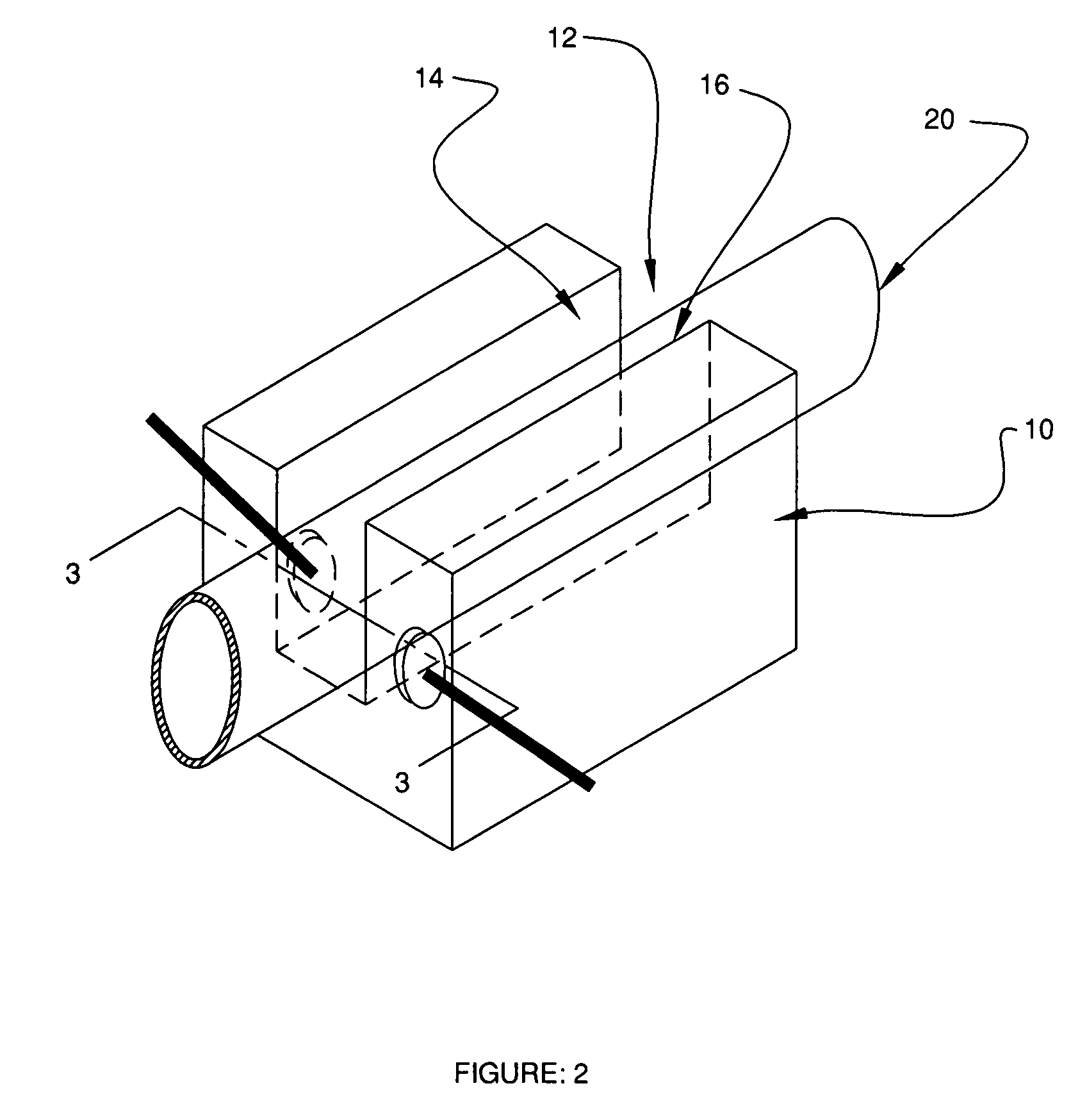
[0016]Referring to FIGS. 2 and 3 the system has a sensor head 10 similar to that described with respect to FIG. 1. The head 10 of the non-invasive sensor is a block of a plastic material such as UDELL polysulfone resin manufactured by Solvay Advanced Polymers. The head 10 is illustratively shown as being of a generally rectangular shape and can be molded by any suitable technique. In the head 10 there is a longitudinal slot 12 that has opposing side walls 14 and 16. A tube 20 of flexible and elastically outwardly expansible material having a liquid flowing in it is to be placed in the slot 12. Typical materials for the tube are silicone, vinyl plastic, polyethylene or flexible TEFLON, with the latter two materials being somewhat more rigid than the first two. The tube 20 typically is to have one end connected to the body of a patient and the other end connected to a liquid supply, such as a medicine or saline solution in a suspended bag, or to a machine such as a dialysis machine or...


PUM


Abstract

A system for determining pressure change in a liquid flowing in a tube of an elastic material has a sensor head having a slot and a pair of piezoelectric elements mounted in opposing walls of said slot between which the tube is placed in contact with the opposing elements. An electronic circuit generates periodic bursts of electro-mechanical energy from one of the elements that is transmitted through the tube to be received by the other element to be converted to an electrical signal from which is measured the travel time value of the energy through the tube and liquid therein and the amplitude value of the received signal which values are compared to at least one of base line travel time and amplitude values to determine a change of pressure of the liquid flowing in the tube.

Description

FIELD OF THE INVENTION[0001]The present invention relates to a system using a non-invasive ultrasonic technique to determine internal pressure of a fluid flowing in a flexible tubing.BACKGROUND OF THE INVENTION[0002]In pharmaceutical and medical industries a need exists to determine the pressure of a liquid flowing in a tube or tubing. In such applications the tube is usually of an elastic compressible and expandable material, such as silicone, vinyl plastic, polyethylene or flexible type TEFLON. Determination of the fluid pressure provides useful information regarding presence of flow of the liquid and operation of a pumping mechanism that might be used to supply the liquid in the tube.[0003]Several prior art techniques exist for measuring internal pressure of a liquid flowing in a tube of elastic material on a non-invasive basis, that is, without having to have a component of the instrument come into contact with the liquid. One of these relies on the deformation of the tube wall ...

Claims


Application Information

Patent Timeline
IPC IPC(8): G01F1/66
CPCG01L9/0022
Inventor DAM, NAIM
Owner MEASUREMENT SPEC
Why Eureka
Try Eureka