Methods for extracting oil from tar sand
a technology of oil extraction and tar sand, which is applied in the direction of fluid removal, borehole/well accessories, insulation, etc., can solve the problems of significant wastewater disposal problems, large water supply and abundant energy,
- Summary
- Abstract
- Description
- Claims
- Application Information
AI Technical Summary
Benefits of technology
Problems solved by technology
Method used
Image
Examples
example 1
[0092]Hydrocarbons are extracted from 1 m3 of formation with electrodes 10 meters apart while varying heat treatment time.
Solving equation (7) with l=10 m, shall lead to the following formula (8).
[0093]U=583.1399.3+3166.5t;(8)
Table 4 presents results of calculations of U as a function of t, as well as derivative energy and costs calculations.
[0094]
TABLE 4Calculated processing parameters vs estimated energy costs for the heat treatmentprocess.Current density,Sample heatSample heatRequired EnergyA / m2 (calculatedtreatment timetreatment time ofRequired voltageSupply need, E,using equation (4)of 1 m3 of1 m3 of formation,to performkWh (calculatedand area of 0.1 m2formation, hrsdaysoperation, Vper equation (3))used above)10.04234,81860.617.524113,439.4216.86.72401011,840.41,6835.92641111,823.21,845.95.97203011,715.84,941.45.86
example 2
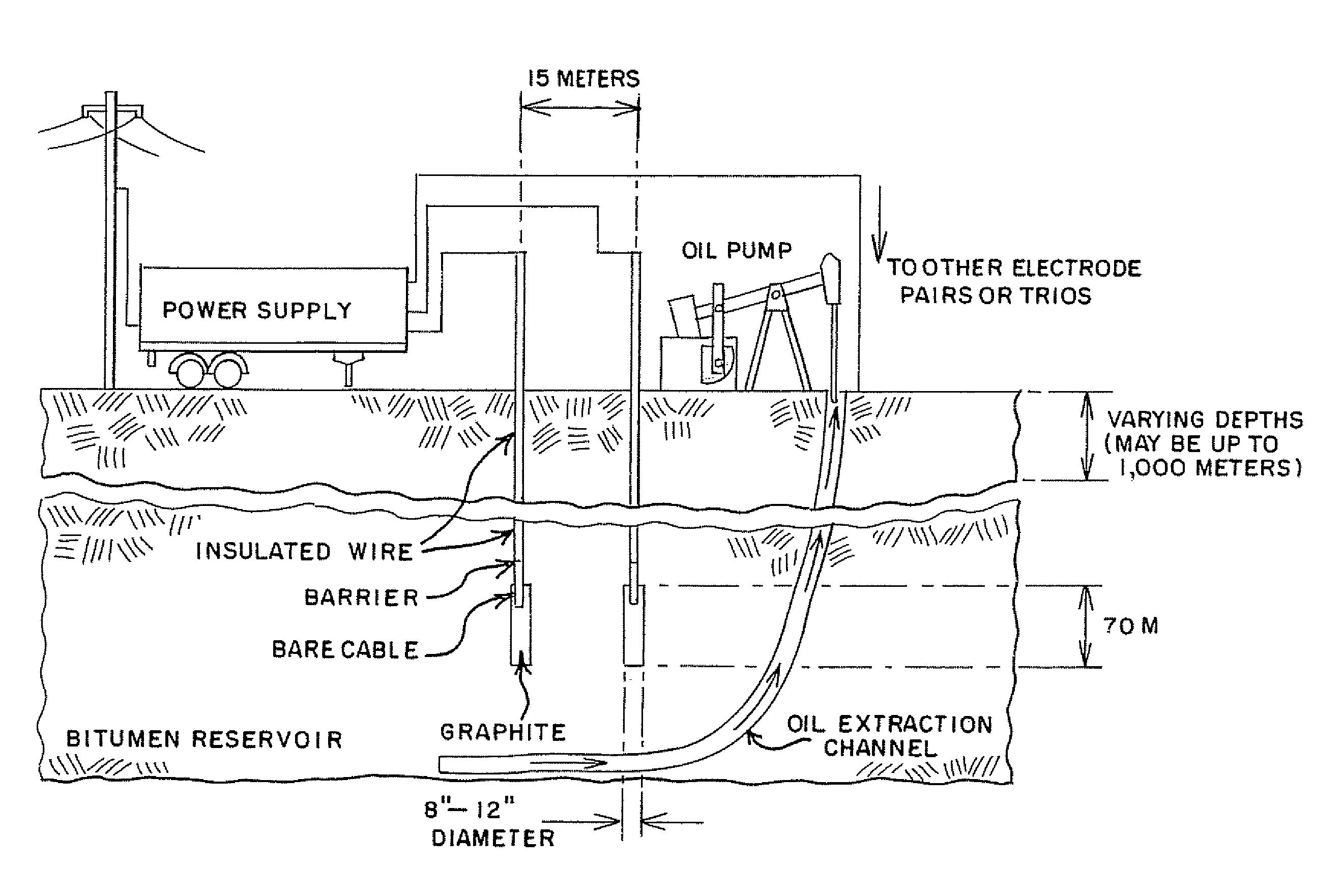
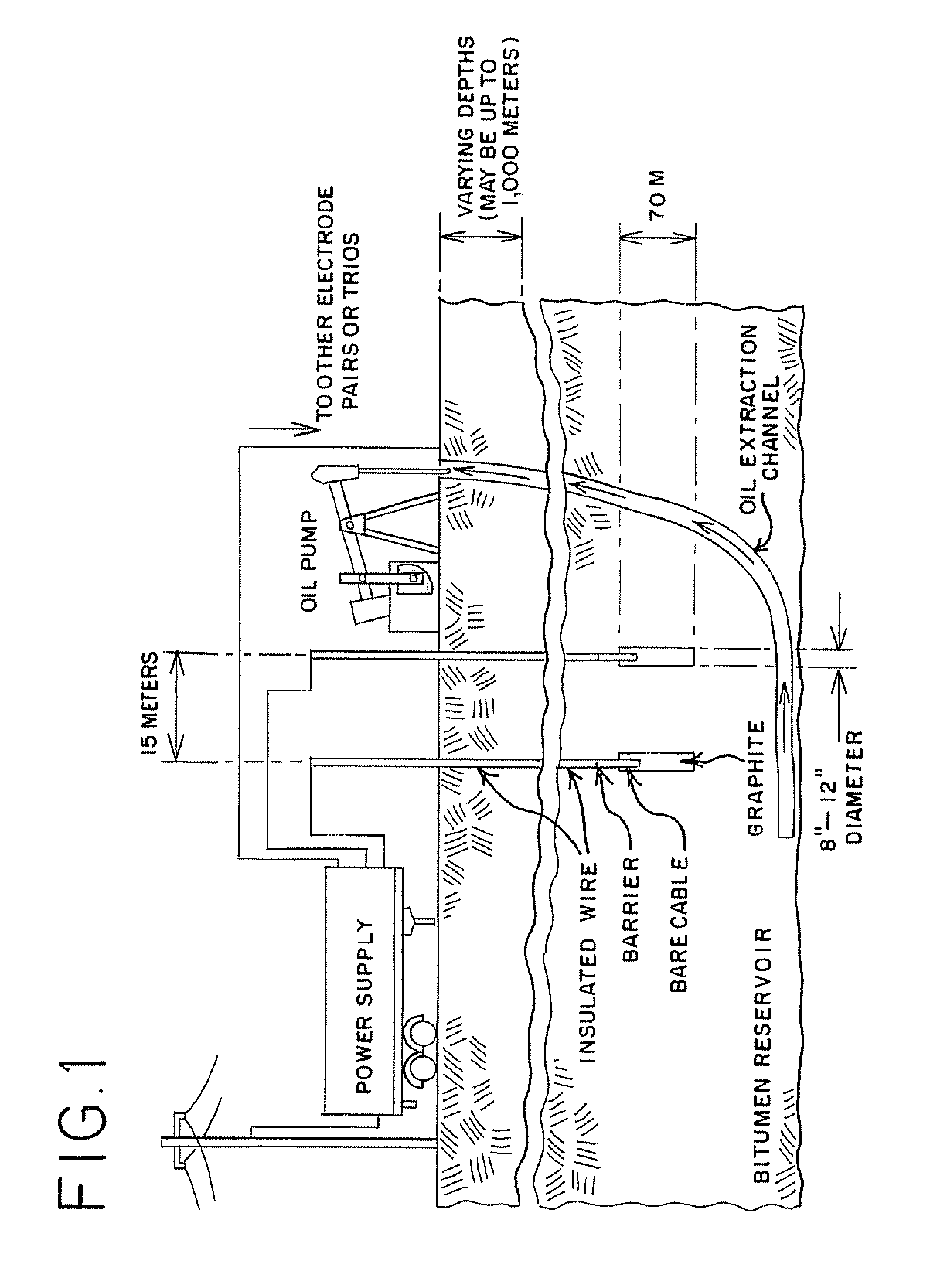
[0095]Hydrocarbons are extracted using two 12″ (0.305 m) electrodes, 70 meters deep 10 meters apart while varying heat treatment time. The volume between the two electrodes is 213.5 m3.
Solving equations (5) and (7) will result in the following formula:
E=Q+E1=763.52t+11,492.7;
[0096]
TABLE 5Calculated processing parameters vs. estimated energy requirement forthe heat treatment process.Current density,Heat treatmentRequired EnergyA / m2 (calculatedEnergytime of 213.5 m3Required voltageSupply need, E,using equation (4)requirement perofHeat treatmentto performkWh (calculatedand electrode areabarrel of oil,formation, hrstime, daysoperation, Vper equation (3))used above)kWh / bbl10.04233,88412,25616.936.624110,788.129,817.25.488.9240108,718.4194,737.54.4580.5264118,694.9213,061.34.3635.2
example 3
[0097]Hydrocarbons are extracted using two 12″ (0.305 m) electrodes, 70 meters deep, 15 meters apart while varying heat treatment time and assuming 100% yield of oil. The volume between the two electrodes is 320.25 m3.
Solving equations (5) and (7) will result in the following formula:
E=Q+E1=1,135.6t+17,239;
[0098]
TABLE 6Calculated processing parameters vs estimated energy costs for the heat treatmentprocess.Current density,Heat treatmentRequired EnergyA / m2 (calculatedEnergytime of 320.25 m3Required voltageSupply need, E,using equation (4)requirement perofHeat treatmentto performkWh (calculatedand electrode areabarrel of oil,formation, hrstime, daysoperation, Vper equation (3))used above)kWh / bbl10.04250,811.618,37416.936.524116,139.944,4935.3788.4120513,407.3153,5114.47305.12401013,016.1289,6394.3575.7
PUM
 Abstract
Description
Claims
Application Information
 - R&D
- Intellectual Property
- Life Sciences
- Materials
- Tech Scout
- Unparalleled Data Quality
- Higher Quality Content
- 60% Fewer Hallucinations
Browse by: Latest US Patents, China's latest patents, Technical Efficacy Thesaurus, Application Domain, Technology Topic, Popular Technical Reports.
© 2025 PatSnap. All rights reserved.Legal|Privacy policy|Modern Slavery Act Transparency Statement|Sitemap|About US| Contact US: help@patsnap.com


