Split magnet ring on a magnetron sputter chamber

a magnetron sputter chamber and split magnet technology, applied in the field of auxiliary magnets, can solve the problems of considerable overhang and unsatisfactory uniformity

Active Publication Date: 2009-11-17
APPLIED MATERIALS INC
View PDF6 Cites 3 Cited by
  • Summary
  • Abstract
  • Description
  • Claims
  • Application Information

AI Technical Summary

Problems solved by technology

In this application, overhang is a considerable problem.
On the other hand, when the Gung configuration is applied to sputtering a tantalum barrier layer between the walls of the via hole and the copper seed layer, the resulting uniformity was not completely satisfactory.

Method used


Image

  • Split magnet ring on a magnetron sputter chamber
  • Split magnet ring on a magnetron sputter chamber
  • Split magnet ring on a magnetron sputter chamber

Examples


Embodiment Construction

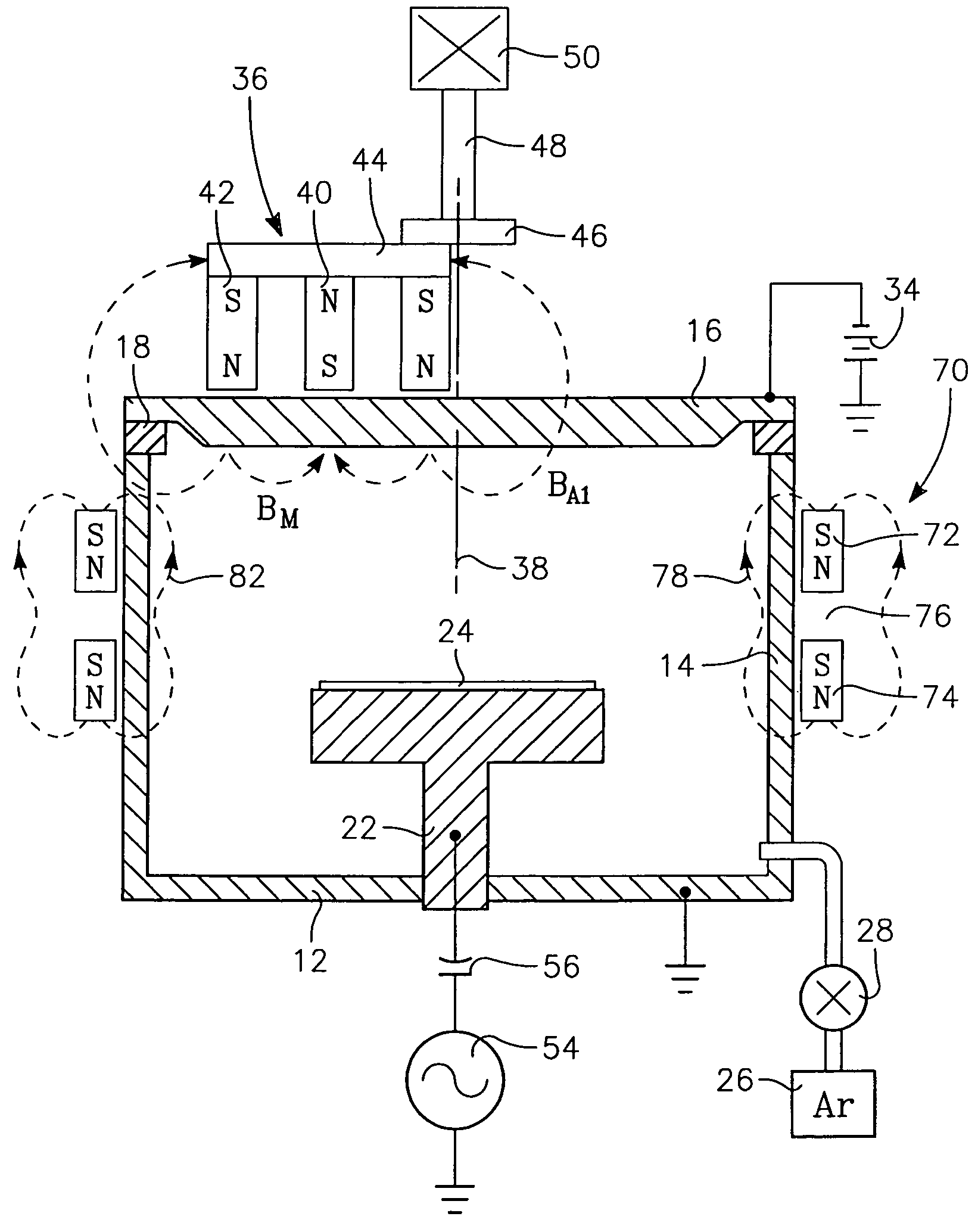
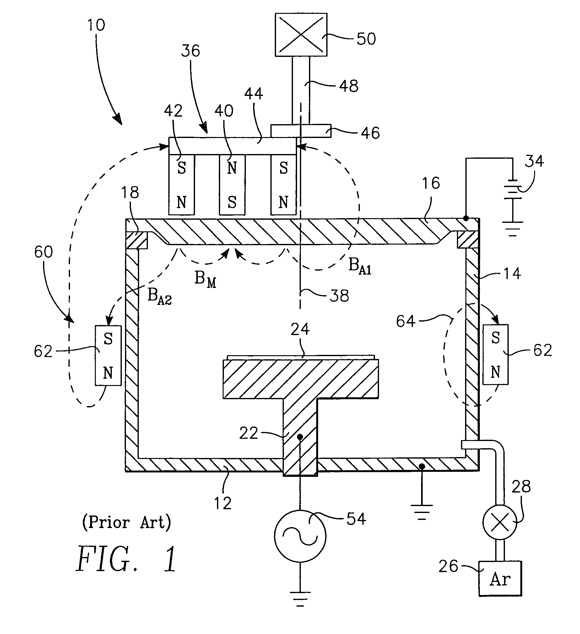
[0024]I believe that the improved uniformity achieved by Gung is in part achieved by the magnet ring 62 producing a generally semi-toroidal magnetic field 64 that resembles a dipole field adjacent the chamber sidewall 14 or the shields on the side of the chamber away from the rotating magnetron 36 but also exists on the side of the chamber 12 temporarily aligned with the rotating magnetron 36. As shown in more detail in the schematic elevation view of FIG. 2, the magnetic field 64 produced by the magnet ring 60 is a magnet dipole field except for unimportant secondary effects due to annular form of the magnet ring 60. Inside the chamber sidewall 14, the dipole field 64 creates a magnetic barrier against the diffusion of the plasma, in particular its electrons, to the grounded chamber sidewall 14. As a result, the plasma containing the sputtered metal ions which diffuses from the target 16 near the magnetron 46 is prevented from diffusing to the grounded wall 14. Such a diffusing pla...


PUM

PropertyMeasurementUnit
diameteraaaaaaaaaa
aspect ratioaaaaaaaaaa
pressureaaaaaaaaaa

Abstract

A split magnet ring, particularly useful in a magnetron plasma reactor sputter depositing tantalum or tungsten or other barrier metal into a via and also resputter etching the deposited material from the bottom of the via onto the via sidewalls. The magnet ring includes two annular magnet rings composed of the same axial polarity separated by a non-magnetic spacing of at least the axial length of one magnet and associated poles. A small unbalanced magnetrons rotates about the back of the target having an outer pole of the same polarity as the ring magnets surrounding a weaker inner pole of the opposite pole.

Description

RELATED APPLICATION[0001]This application claims benefit of provisional application 60 / 663,568, filed Mar. 18, 2005.FIELD OF THE INVENTION[0002]The invention relates generally to sputtering of materials. In particular, the invention relates to auxiliary magnets used to improve uniformity in a magnetron sputter reactor.BACKGROUND ART[0003]Sputtering, alternatively called physical vapor deposition (PVD), is commonly used in depositing layers of metals and related materials in the fabrication of semiconductor integrated circuits. Recent technology developed for copper metallization in silicon integrated circuits has emphasized sputtering of refractory metals such as tantalum for use as a barrier layer in a interconnect hole structure etched into a dielectric and sputtering of copper for use as a seed layer for the final electroplating of copper to fill the hole. The requirements placed upon sputtering have intensified as the diameter of the interconnect hole has shrunk to below 100 nm ...

Claims


Application Information

Patent Timeline
Patent Type & Authority Patents(United States)
IPC IPC(8): C23C14/35
CPCC23C14/165C23C14/35H01J37/3461H01J37/3408H01J37/3405
Inventor FU, XINYU
Owner APPLIED MATERIALS INC
Why Eureka
Try Eureka