
Method of measuring aberrations and correcting aberrations using Ronchigram and electron microscope

a technology of electron microscope and aberration measurement, applied in the field of electron microscope, can solve the problem of inability to obtain ultrahigh-resolution images

Active Publication Date: 2009-11-17
JEOL LTD
View PDF10 Cites 10 Cited by
  • Summary
  • Abstract
  • Description
  • Claims
  • Application Information

AI Technical Summary

Benefits of technology

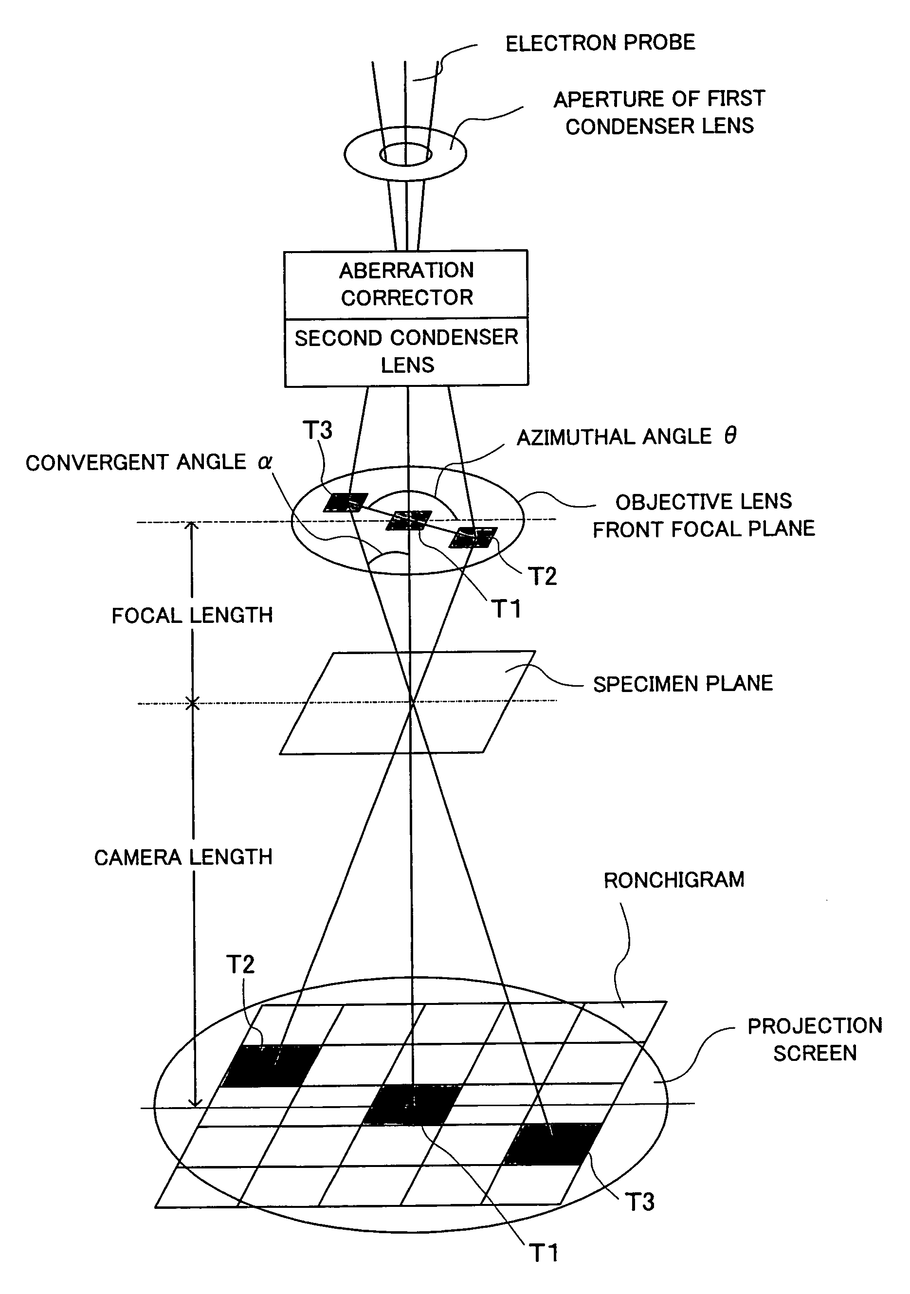
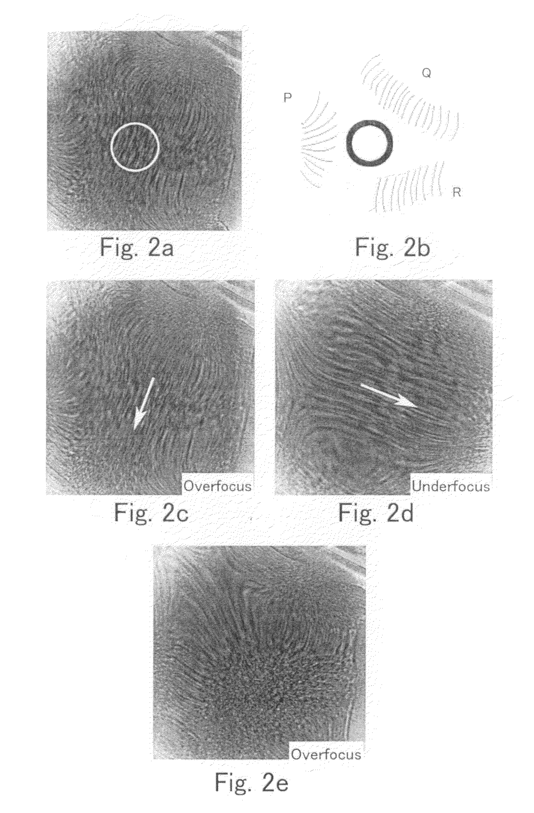
The present invention provides a method and apparatus for measuring and correcting aberrations in an electron microscope. The method involves using a Ronchigram, which is a long amorphous portion of a specimen, to measure residual aberrations through the observation of the Ronchigram. The residual aberrations can be adjusted through observation of the Ronchigram. The invention also provides a method for automatically correcting aberrations using the Ronchigram. The technical effects of the invention include improved accuracy in measuring and correcting aberrations in an electron microscope.

Problems solved by technology

There is the problem that ultrahigh-resolution images cannot be obtained due to the introduced aberrations.

Method used


Image

  • Method of measuring aberrations and correcting aberrations using Ronchigram and electron microscope
  • Method of measuring aberrations and correcting aberrations using Ronchigram and electron microscope
  • Method of measuring aberrations and correcting aberrations using Ronchigram and electron microscope

Examples


Embodiment Construction

[0040]Embodiments of the present invention are hereinafter described in detail with reference to the accompanying drawings.

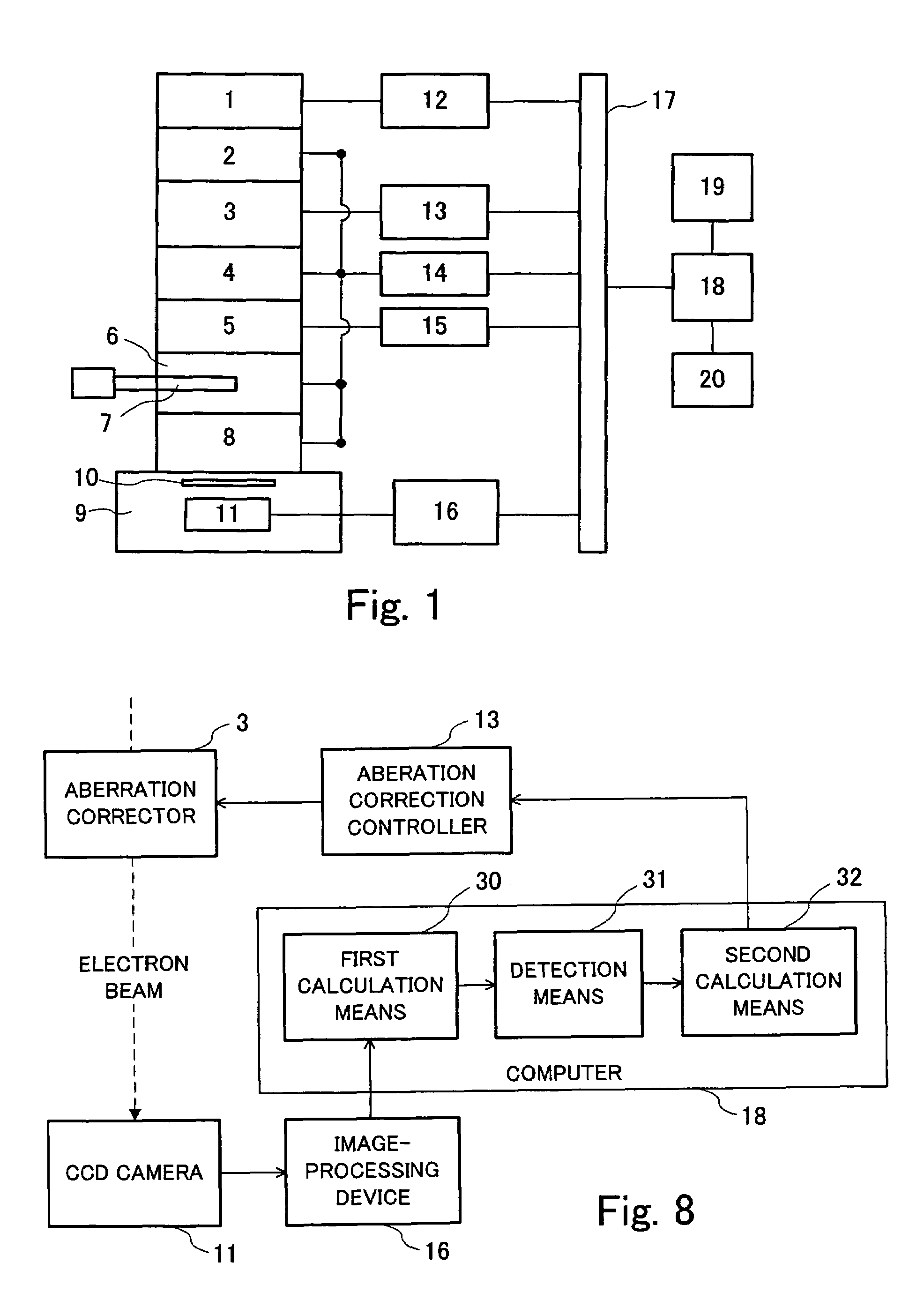
[0041]FIG. 1 is a block diagram showing an example of apparatus for implementing an embodiment of the present invention. The apparatus has an electron gun 1 for producing an electron beam, a first condenser lens 2 including a stigmator (i.e., astigmatism-correcting element), and an aberration corrector 3 incorporated in the illumination system and including a stigmator for correcting aberrations in the illumination system of the apparatus. The aberration corrector 3 of the illumination system includes electron beam-deflecting elements and the stigmator.

[0042]The apparatus further includes a second condenser lens 4 having deflectors, a scan assembly 5 for scanning an electron beam, an objective lens 6, a specimen stage 7, an imaging lens system 8 including intermediate and projector lenses, and an observation chamber 9 for observing a projected image. A projectio...


PUM

PropertyMeasurementUnit
timeaaaaaaaaaa
electron microscopeaaaaaaaaaa
electron beam scanningaaaaaaaaaa

Abstract

A method and apparatus for correcting aberrations using a Ronchigram. A STEM apparatus has first calculation means for taking autocorrelation of minute regions on a Ronchigram of an amorphous specimen, detection device for detecting aberrations in the beam formed from local angular regions on an aperture plane from the autocorrelation or from Fourier analysis of the autocorrelation, second calculation device for calculating the aberrations based on the results of the detection, and control device for controlling operation for correcting the aberrations based on results of calculations performed by the second calculation device.

Description

BACKGROUND OF THE INVENTION[0001]1. Field of the Invention[0002]The present invention relates to an electron microscope for imaging a specimen by focusing an electron beam (hereinafter may be referred to as the “electron probe” or simply as the “probe”) onto the specimen, scanning the probe over the specimen, detecting the electrons transmitted through the specimen by an electron detector, and visualizing the output signal from the detector in synchronism with the electron beam scanning. More particularly, the invention relates to a method of measuring aberrations by an electron microscope equipped with an illumination system aberration corrector by the use of a Ronchigram and to a method and apparatus for correcting aberrations.[0003]2. Description of Related Art[0004]In transmission electron microscopy, a method of imaging a specimen by focusing an electron beam onto the specimen, scanning the beam over the specimen, detecting the electrons transmitted through the specimen by an e...

Claims


Application Information

Patent Timeline
Patent Type & Authority Patents(United States)
IPC IPC(8): G01N23/00G21K7/00
CPCG01N23/04H01J37/153H01J37/265H01J2237/282H01J2237/2487H01J2237/2802H01J2237/1534
Inventor SAWADA, HIDETAKASANNOMIYA, TAKUMI
Owner JEOL LTD
Learn More