Mapping images from one or more sources into an image for display

a technology of visual images and images, applied in static indicating devices, refuse gathering, instruments, etc., can solve the problems of insufficient vertical visualization above and below the aircraft, inability to provide adequate vertical visualization, and inability to accurately provide images to the pilot, so as to reduce the number of anomalies and reduce their intensity

Inactive Publication Date: 2009-11-17
THE BOEING CO
View PDF42 Cites 71 Cited by
  • Summary
  • Abstract
  • Description
  • Claims
  • Application Information

AI Technical Summary

Benefits of technology

[0013]The systems and methods of the present invention reduce issues with regard to parallax in the displayed images. Specifically, the systems and methods of the present invention create one or more artificial mapping surfaces at a selected distance in front of the vehicle or point of interest. The artificial mapping surface allows the various images from the different sources to be correlated by a common frame of reference, with all of the images from each source being projected onto the mapping surface in the form of a tile that represents the desired surface area coverage. The mapping surface creates a frame of reference for correlating the difference in line of sight to an object of interest between the observer and the sources due to the distance separation between the observer and the sources.
[0014]Further, the sources, display, and mapping surface all have different coordinate systems. The systems and methods of the present invention create a common or primary coordinate system and transform the images from each of these components to the common or primary coordinate system. This, in turn, allows the systems and methods of the present invention to correlate the images from the various sources and provide them to the user in the viewer's frame of reference to thereby reduce and possibly eliminate parallax.
[0015]In addition to correcting for parallax, the systems and methods of the present invention also provide improved methods for stitching distributed aperture images together into a seamless mosaic. The systems and methods of the present invention overlap the edges of tile images received from the sources of the same type that are taken of adjacent or overlapping fields of view. In the overlapped region between the two tile images, the systems and methods of the present invention define blend zones that consist of inner and outer edges. In the blend zones, the systems and methods of the present invention alter the intensity of individual pixels of each tile image so as to blend the two tile images together at the blend zones. The pixels of the left image in the blend zone are tapered from an intensity value of one (1) for the pixels adjacent to the left edge of the blend zone to an intensity value of zero (0) for the pixels adjacent to the right edge of the blend zone. In an opposite manner, the pixels of the right image in the blend zone are tapered from an intensity value of zero (0) for the pixels adjacent to the left edge of the blend zone to an intensity value of one (1) for the pixels adjacent to the right edge of the blend zone. This alteration of pixel intensity values in the blend zone provides an enhanced stitch between the two images. Top and bottom stitching is performed in the same manner.
[0016]The systems and methods of the present invention also provide a method for overlaying or fusing images from different types of sources. Specifically, the system of the present invention may include two different types of sources having either the same or overlapped fields of view. The sources provide different images of the same field of view; each source having associated advantages and disadvantages. For example, one source could be a video camera that provides images that may be affected by the amount of light or visibility and the other source may be an infrared sensor that provides images based on heat sensing. The systems and methods of the present invention provide a method for overlaying or fusing the images from these sources together to provide an enhanced image.
[0018]The systems and methods of the present invention further include methods for reducing the number of anomalies in a given displayed image. The systems and methods of the present invention evaluate the intensity value associated with each pixel in a tile image. If a pixel or a series of pixels have intensity values that are excessive compared to neighboring pixels, the systems and methods of the present invention may decrease their intensity based on an average intensity value from neighboring pixels.

Problems solved by technology

However, there are instances where these various instruments become the pilot's only resource for information because the pilot's vision is hindered.
Further, some visual hindrances are due to the field of view limitations of the aircraft itself.
Many aircraft cockpits have a field of view that is typically limited to a forward facing area that does not provide the pilot with adequate visualization to the sides and rear of the aircraft and also does not provide adequate vertical visualization above and below the aircraft.
However, there are some limitations to these systems that can cause the images provided to the pilot to either be less accurate or include anomalies that may distract the pilot's view.
For example, one issue relates to the spacing of sensors relative to each other and relative to the pilot's position or in the case of stored synthetic data, the difference in perspective between the synthetic data and the other sensors and pilot's position.
This physical distance between the sources relative to each other and the cockpit may cause a skewing of the images provided to the pilot.
As such, when viewing the images from the sensor point of view, the pilot is not provided with an accurate representation of the location of the object relative to his position in the aircraft in their overlapping field of view.
Another issue relates to tiling of several images together to create a composite image.
These seams disrupt viewing of the composite image and can make it harder for the pilot to view the image as a whole.
While this technique is an improvement over the conventional technique of abutting adjacent images, there may still be perceived discontinuity between the images.
A further issue relates to the limitations of a particular type of sensor to provide the best imaging for a given situation.
For example, in twilight conditions, a video camera will still provide a discernable visual image, but the image will be degraded in detail due to the low light or obstructed conditions.
Further, an infrared sensor will provide imaging based on heat sensing, but the image from an infrared sensor will not have the benefit of the ambient light still available at twilight.
As such, the pilot does not have the best images available for viewing.

Method used


Image

  • Mapping images from one or more sources into an image for display
  • Mapping images from one or more sources into an image for display
  • Mapping images from one or more sources into an image for display

Examples


Embodiment Construction

[0040]The present invention now will be described more fully hereinafter with reference to the accompanying drawings, in which preferred embodiments of the invention are shown. This invention may, however, be embodied in many different forms and should not be construed as limited to the embodiments set forth herein; rather, these embodiments are provided so that this disclosure will be thorough and complete, and will fully convey the scope of the invention to those skilled in the art. Like numbers refer to like elements throughout.

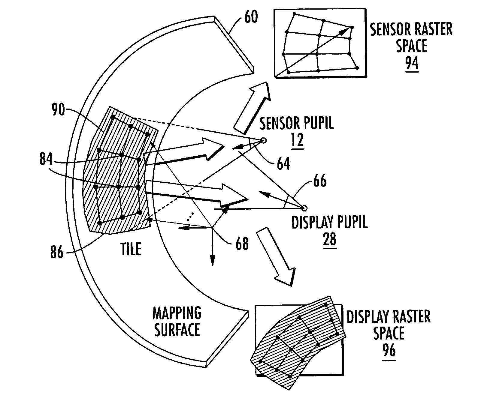
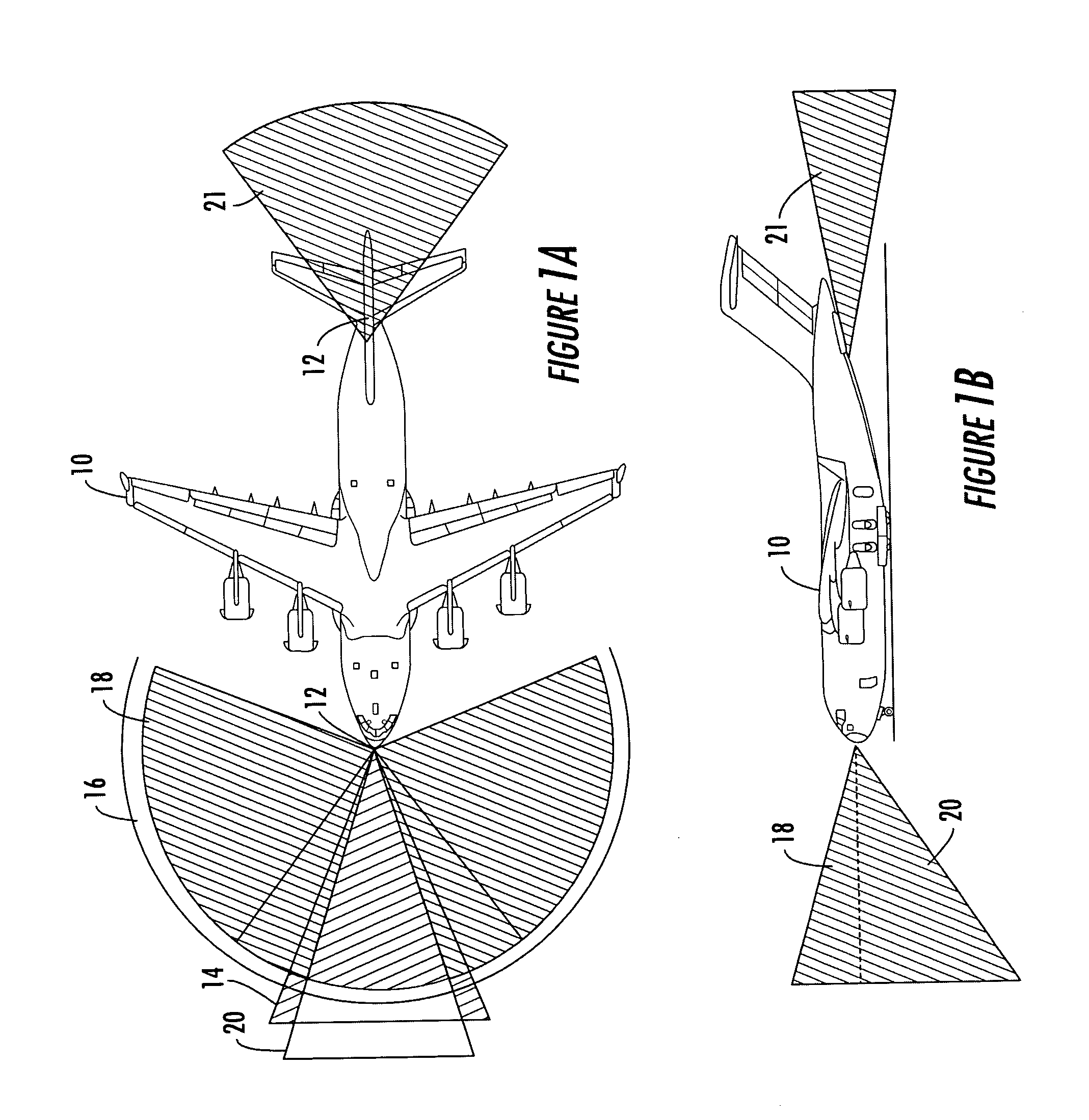
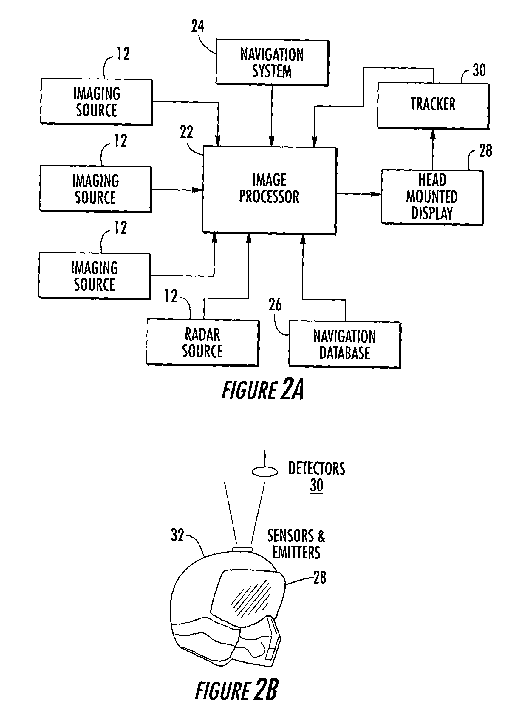
[0041]The present invention provides systems and methods for use in enhanced vision displays. The systems and methods of the present invention receive image data from a plurality of sources located at different positions on a vehicle or in an area of interest. The systems and methods assimilate the images from each source into a composite image. The system may also be provided with synthetic data from a data source. Both sensors and synthetic data sources ...


PUM


Abstract

The present invention provides systems and methods that provide images of an environment to the viewpoint of a display. The systems and methods define a mapping surface at a distance from the image source and display that approximates the environment within the field of view of the image source. The system methods define a model that relates the different geometries of the image source, display, and mapping surface to each other. Using the model and the mapping surface, the systems and methods tile images from the image source, correlate the images to the display, and display the images. In instants where two image sources have overlapping fields of view on the mapping surface, the systems and methods overlap and stitch the images to form a mosaic image. If two overlapping image sources each have images with unique characteristics, the systems and methods fuse the images into a composite image.

Description

BACKGROUND OF THE INVENTION[0001]1. Field of Invention[0002]The present invention relates to vision display systems used to provide a user with a visual display of a field of interest, and more particularly to systems and methods that combine images from a plurality of sources to provide a coherent view of a field of interest.[0003]2. Description of Related Art[0004]Despite the advent of many flight navigational aids, one of the most important tools for navigation of aircraft remains visual navigation. Many of today's aircrafts include various safety features such as on board radar, ground proximity warning systems, etc. that provide a pilot with added information about the airspace surrounding the aircraft. These systems are a tremendous resource to aid the pilot in obtaining better situational awareness during flight, by allowing the pilot to further interpret what he or she is visually observing. However, there are instances where these various instruments become the pilot's only...

Claims


Application Information

Patent Timeline
Patent Type & Authority Patents(United States)
IPC IPC(8): G06T15/10G09G5/00G06T15/04H04N7/18
CPCG06T15/10G06T15/04G06T15/205B65D33/08B65F1/002B65F1/12B65F2210/126B65F2210/167
Inventor BERNIER, KENNETH L.
Owner THE BOEING CO
Why Eureka
Try Eureka