
Application non disruptive task migration in a network edge switch

Active Publication Date: 2009-11-17
PALO ALTO NETWORKS INC
View PDF21 Cites 19 Cited by
  • Summary
  • Abstract
  • Description
  • Claims
  • Application Information

AI Technical Summary

Benefits of technology

[0017]The present invention provides a network edge switch that allows code and / or configuration changes to be performed with zero down time and zero application disruption (i.e., no datagram loss, no datagram reordering and no datgaram duplication)—and which does present a “single system” view to a network administrator who will control and manage the switch. Such changes can be performed at any time and at an arbitrarily high frequency, and can be initiated by a human or by a programmed automated process.
[0018]This is accomplished by having at least two forwarding engines within the packet switch controlled by a control processor. A well-defined protocol among these elements allows the control processor to direct task migration from one forwarding engine to a second forwarding engine with no disruption to applications. Packets which initially flow through the first forwarding engine are migrated to the second forwarding engine that can be running different code or have a different configuration.

Problems solved by technology

Unfortunately, the switch was unable to perform its functions while the code is changed and / or the configuration data is modified.
This kind of re-routing usually results in a period of instability involving datagram loss, datagram reordering and / or datagram duplication, all of which are disruptive to applications running on host computers connected to these networks.
Even packet switch down time scheduled well in advance can be very costly, especially in today's high-speed networks.
Datagram loss for more than a few hundred milliseconds causes a severe degradation in quality, even for a single subscriber session, and can render network service unacceptable for many network applications, such as real-time voice over IP.
For switches deployed in service provider networks with large numbers of subscriber sessions, even a tiny amount of datagram loss has an unacceptable impact on subscriber revenue or satisfaction.
Managing multiple systems is cumbersome and expensive, compared to managing a single system that can perform all the functions of the multiple system alternative; hence in packet switching the requirement for a “single system” view has evolved.

Method used


Image

  • Application non disruptive task migration in a network edge switch
  • Application non disruptive task migration in a network edge switch
  • Application non disruptive task migration in a network edge switch

Examples


Embodiment Construction

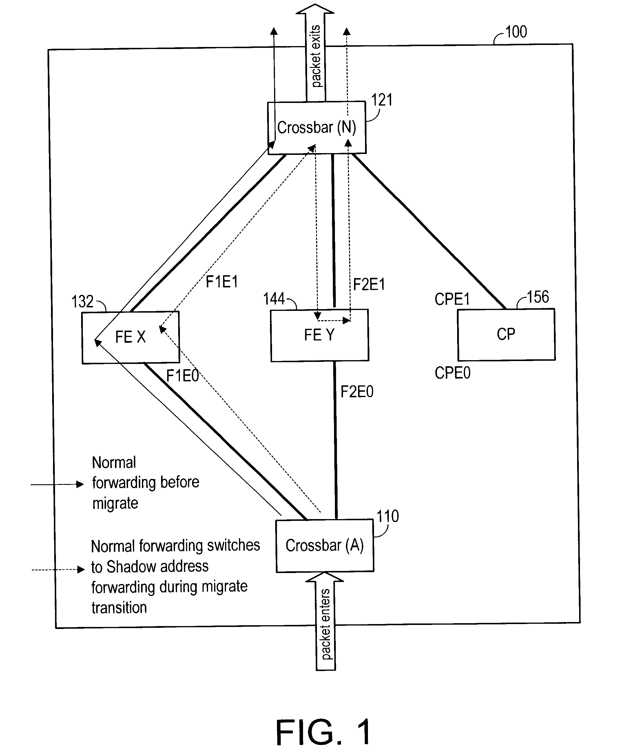
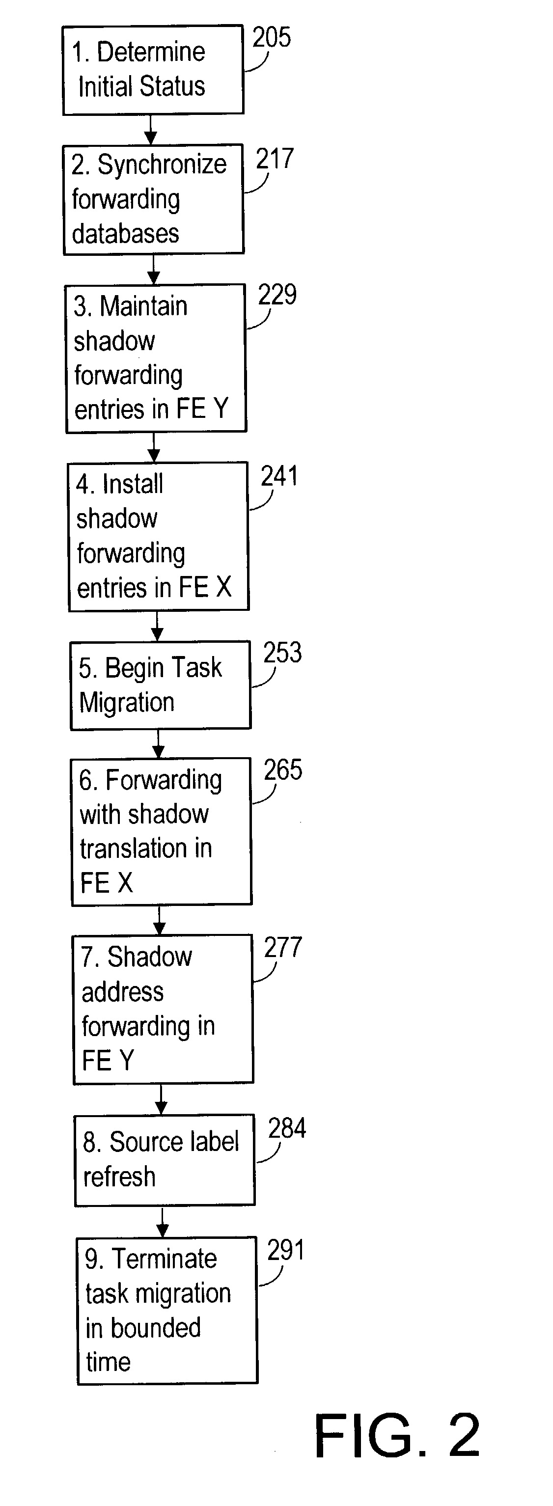
[0030]The present invention in accordance with some embodiments of a network edge switch allows tasks to migrate from one Forwarding Engine (FE) to another FE with no application disruption via messages that synchronize address forwarding tables, establish a microflow to enable packet routing during the transition from one FE to another, and complete and terminate the task migration process without application disruption.

[0031]The invention is applicable to any device that installs and operates as an edge switch for a packet-switched network, including, for example, a transparent Ethernet switch, that performs various packet transformations at Layer 2 (e.g., Ethernet) in the OSI reference model or at multiple layers (Layers 2 through 7).

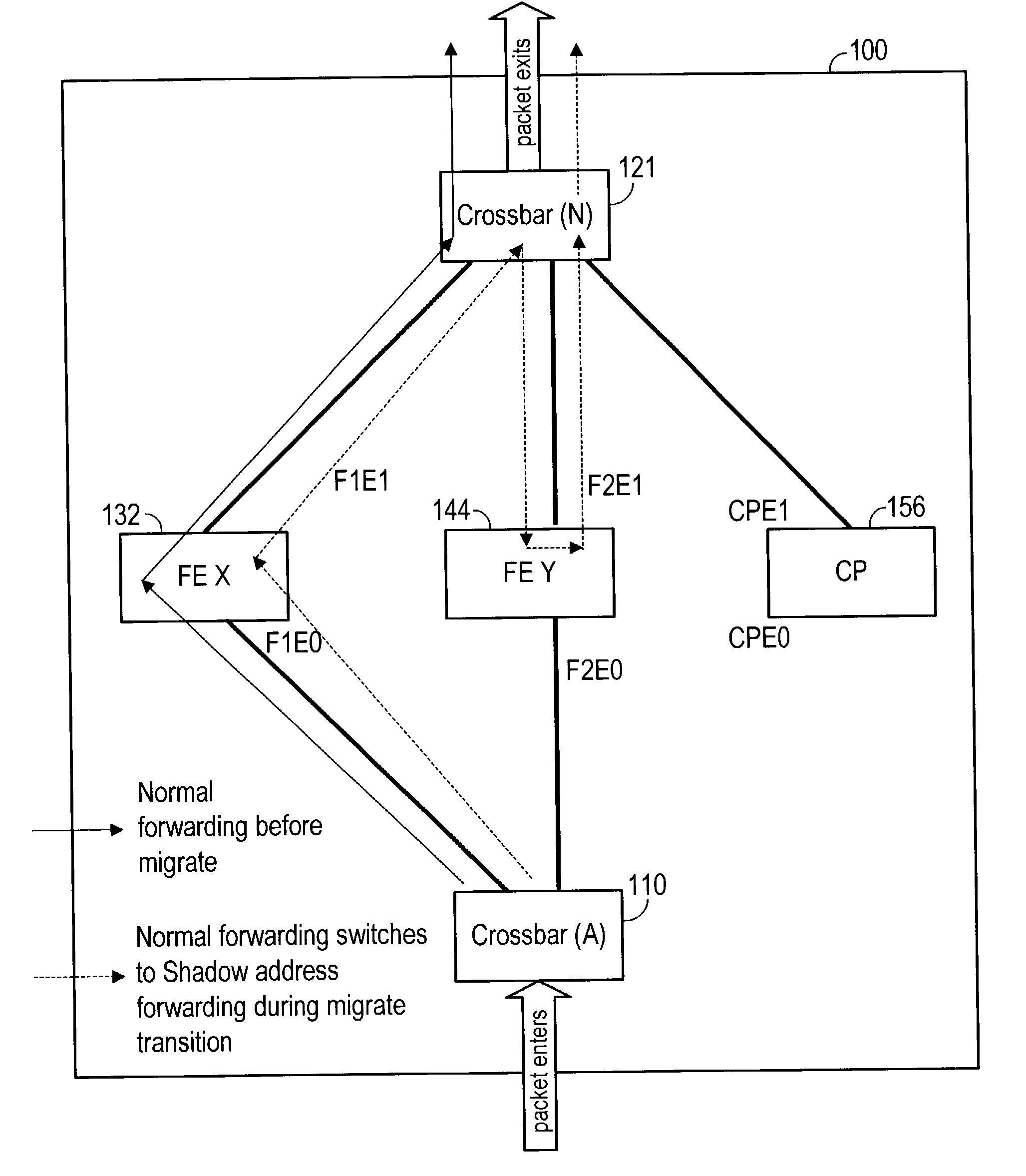
[0032]A block diagram view of packet switch 100 capable of application non-disruptive task migration is shown in FIG. 1. Crossbar (A) 110 represents the Access side of switch 100, Crossbar (N) 121 represents the Network side and data flow is shown fo...


PUM


Abstract

An apparatus and a method are described for zero packet loss task migration in an network switch in a computer network. The invention relates to active or programmable networks, i.e. networks based on packet switching algorithms and switch configurations which are subject to change. A well-defined protocol enables an intelligent switch to migrate tasks from one forwarding engine to another without any packet loss. This enables the algorithms and configurations of the switch to be updated or modified arbitrarily.

Description

CROSS-REFERENCE TO APPENDIX[0001]Appendix A, which is part of the present disclosure, contains exemplary control message formats for an Ethernet packet switch, in accordance to some embodiments of the present invention. Appendix A contains material which is subject to copyright protection. The copyright owner has no objection to the facsimile reproduction by anyone of the patent document or the present disclosure, as it appears in the Patent and Trademark Office patent files or records, but otherwise reserves all copyright rights whatsoever.BACKGROUND OF THE INVENTION[0002]1. Field of the Invention[0003]The present invention relates generally to computer networks and, more specifically, to active or programmable networks, i.e., networks based on datagram based packet switching algorithms and switch configurations, which are subject to constant change over time. In datagram-based packet switching, packets are switched and routed independently of each other.[0004]2. Related Art[0005]N...

Claims


Application Information

Patent Timeline
IPC IPC(8): H04L12/28H04L12/56H04L45/74
CPCH04L45/74H04L49/65H04L45/44H04L49/552H04L49/101H04L49/351
Inventor BHASKARAN, SAJIT
Owner PALO ALTO NETWORKS INC
Learn More