Frequency converter capable of preventing level of intermediate frequency signal from lowering due to rise in temperature

a technology of intermediate frequency signal and temperature rise, which is applied in the field of frequency converters, can solve the problems of reducing the oscillation power, reducing the gain of the mixer, and reducing the oscillation speed, so as to prevent the oscillation speed from lowering and prevent the level of an intermediate frequency signal from lowering

Inactive Publication Date: 2009-11-17
ALPS ALPINE CO LTD
View PDF44 Cites 13 Cited by
  • Summary
  • Abstract
  • Description
  • Claims
  • Application Information

AI Technical Summary

Benefits of technology

[0011]The invention is designed to solve the above-mentioned problem, and it is an object of the invention to prevent oscillation from stopping when an oscillation frequency is lowered and to prevent the level of an intermediate frequency signal from lowering due to a rise in temperature.
[0020]According to the invention, the frequency converter includes the mixer that frequency-converts the received signal to an intermediate frequency signal and has the mixer transistor; an oscillation circuit that supplies an local oscillation signal to the mixer and has an oscillation transistor; a resonating circuit coupled to the oscillation transistor and having the varactor diode, the control voltage for controlling an oscillation frequency being applied to the cathode of the varactor diode; and a bias power supply for setting the collector bias current of the mixer transistor and the collector bias current of the oscillation transistor. In addition, the received signal and the local oscillation signal are input to the mixer transistor, and when the control voltage is equal to or smaller than the first predetermined value, an output voltage of the bias power supply is set to be increased so that at least one of the collector bias current of the mixer transistor and the collector bias current of the oscillation transistor can be increased. Accordingly, even though a Q-factor decreases due to an increase of a resistance component of the varactor diode when the control voltage is low, a gain of the oscillation transistor or the mixer transistor increases. As a result, it is possible to prevent the oscillation from stopping and to raise the level of the intermediate frequency signal.
[0021]Further, according to the invention, since the output voltage of the bias power supply has a positive temperature coefficient, it is possible to prevent the loop gain of the oscillation circuit from decreasing or to prevent the conversion efficiency of the mixer from lowering by increasing the collector current of the oscillation transistor or the collector current of the mixer transistor at the time of the rise in temperature.

Problems solved by technology

As a result, the loop gain of the oscillation circuit becomes insufficient, which may reduce the oscillation power, and in an extreme case, the oscillation may stop.
In addition, the gain of the mixer is also decreased due to the rise in temperature.

Method used


Image

  • Frequency converter capable of preventing level of intermediate frequency signal from lowering due to rise in temperature
  • Frequency converter capable of preventing level of intermediate frequency signal from lowering due to rise in temperature
  • Frequency converter capable of preventing level of intermediate frequency signal from lowering due to rise in temperature

Examples


Embodiment Construction

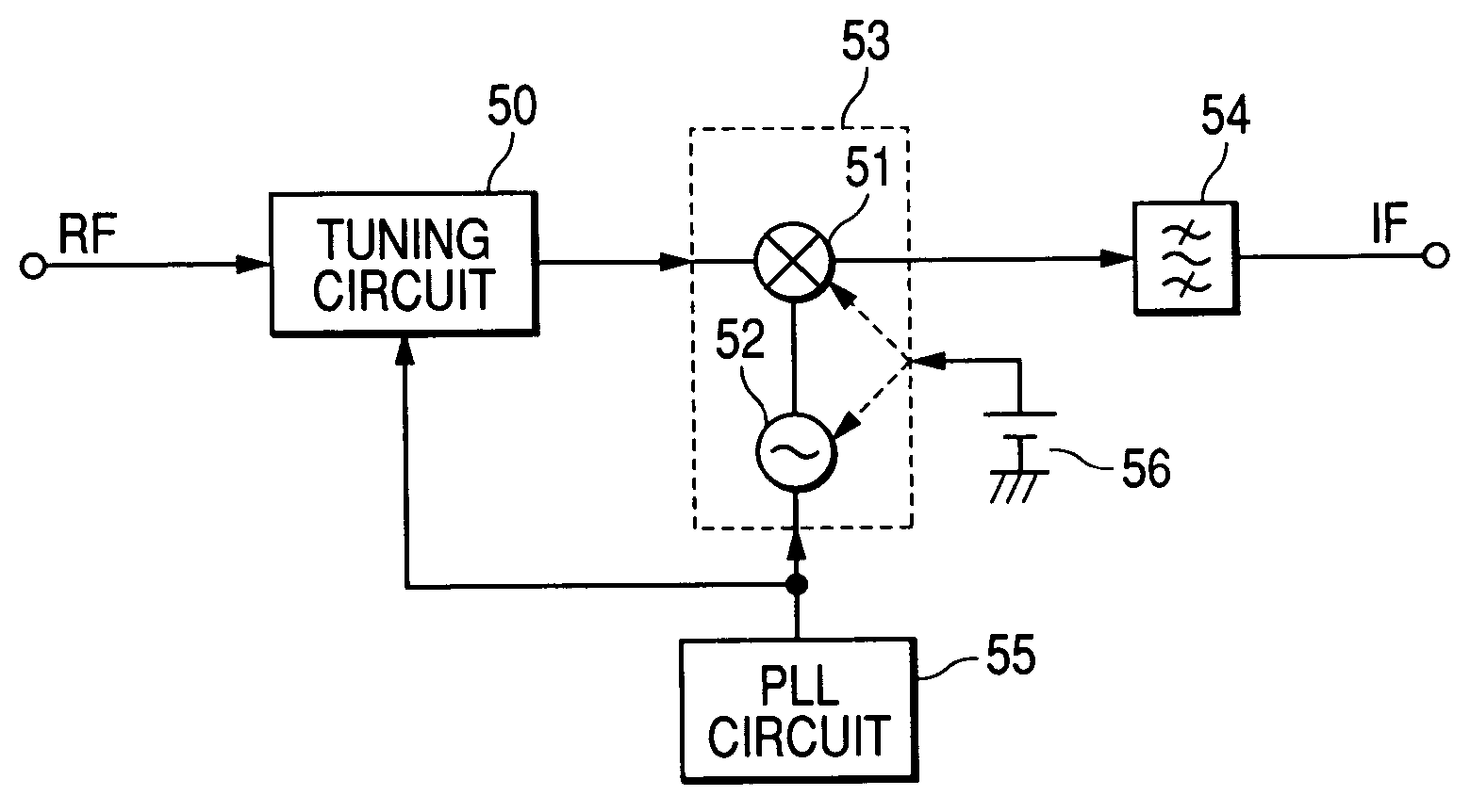
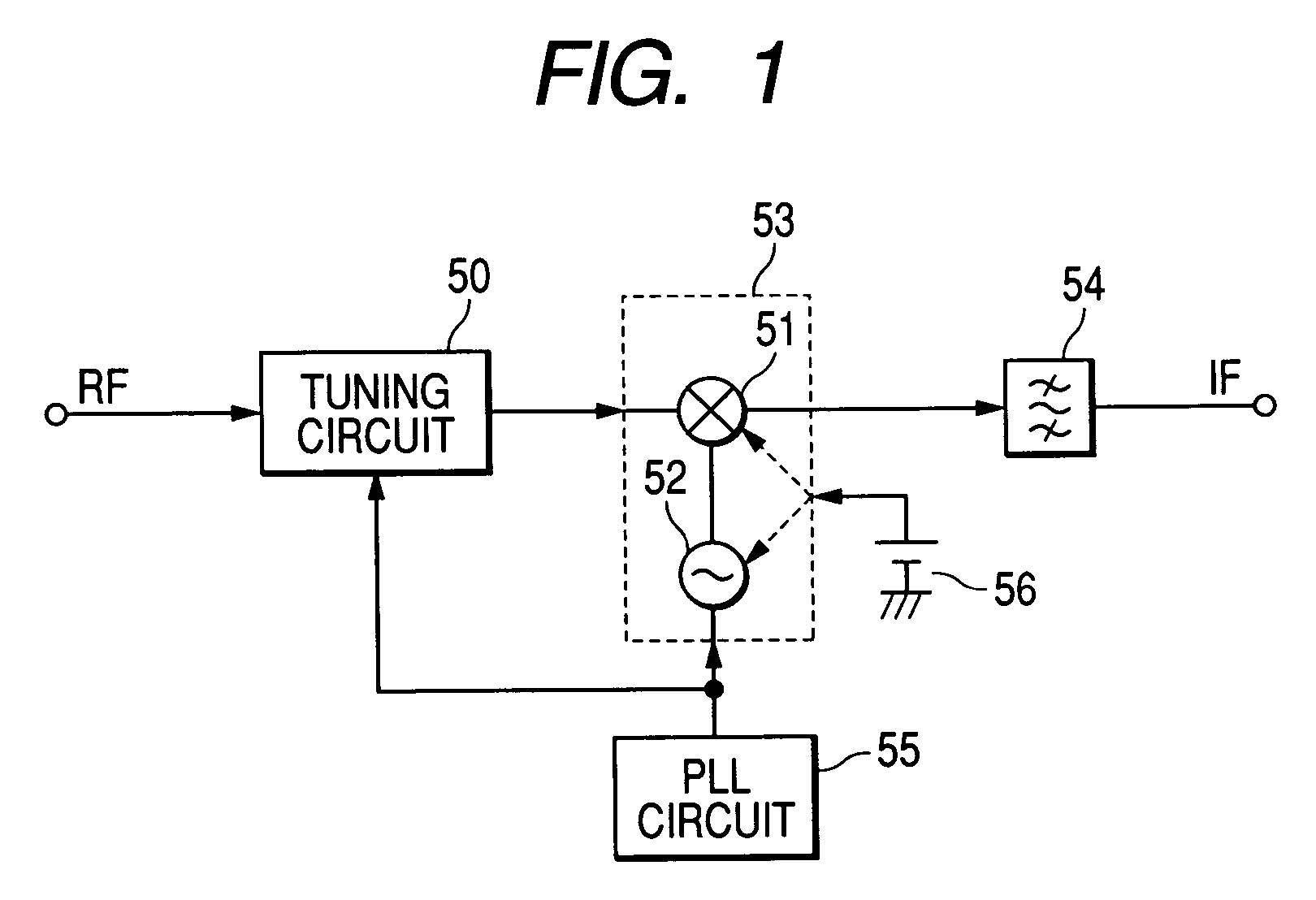
[0036]FIG. 1 shows a basic configuration of a television tuner to which a frequency converter of the invention is applied. A television signal (RF) is input to a mixer 51 through a tuning circuit 50 having a varactor diode (not shown). A local oscillation signal is supplied to the mixer 51 from an oscillation circuit 52. The oscillation circuit 52 also has a varactor diode (not shown). The mixer 51 and the oscillation circuit 52 form the frequency converter 53. An intermediate frequency signal (IF) output from the mixer 51 is supplied to a subsequent-stage circuit through an intermediate frequency tuning circuit 54. A tuning frequency of the tuning circuit 50 and an oscillation frequency of the oscillation circuit 52 are controlled by a PLL circuit 55. That is, a control voltage Vt output from the PLL circuit 55 is applied to the varactor diode of the tuning circuit 50 and the varactor diode of the oscillation circuit 52. If the control voltage Vt increases, the tuning frequency and...


PUM


Abstract

There is provided a bias power supply for setting a collector bias current of a mixer transistor and a collector bias current of an oscillation transistor. When a control voltage is equal to or smaller than a first predetermined value, an output voltage of the bias power supply is set to be increased so that at least one of the collector bias current of the mixer transistor and the collector bias current of the oscillation transistor can be increased.

Description

BACKGROUND OF THE INVENTION[0001]1. Field of the Invention[0002]The present invention relates to a frequency converter used for a television tuner or the like.[0003]2. Description of the Related Art[0004]FIG. 7 shows a conventional oscillation circuit used for a VHF television tuner, for example, and the oscillation circuit includes a first oscillation transistor 2 and a second oscillation transistor 3 provided within an integrated circuit 20 and a resonating circuit 4 provided outside the integrated circuit 20. The first and second oscillation; transistors 2 and 3 are differentially connected to each other.[0005]The resonating circuit 4 provided outside the integrated circuit 20 is coupled to a base of the first oscillation transistor 2 and a collector of the second oscillation transistor 3 through a terminal 20a. The resonating circuit 4 includes an inductive element 4a and a varactor diode 4b, and one end of the resonating circuit 4 is connected to the terminal 20a and the other ...

Claims


Application Information

Patent Timeline
Patent Type & Authority Patents(United States)
IPC IPC(8): H04B1/16
CPCH03D7/1425H03D7/1433H03D7/1458H03D7/1408H03D2200/0043H03D2200/0025
Inventor YAMAMOTO, MASAKI
Owner ALPS ALPINE CO LTD
Why Eureka
Try Eureka