Method and device for storing a traction chain

a traction chain and self-bracing technology, applied in the direction of driving chains, portable lifting, lighting and heating apparatus, etc., can solve the problems of large space and large system, and achieve the effect of little friction

Inactive Publication Date: 2009-11-24
HOF SONDERANLAGENBAU
View PDF14 Cites 12 Cited by
  • Summary
  • Abstract
  • Description
  • Claims
  • Application Information

AI Technical Summary

Benefits of technology

[0008]A method implemented according to this technical teaching and a device configured according to this technical teaching have the advantage that the traction chain can be stored in the region located next to the actual drive wheel by winding it about a winding apparatus. Usually, in the transport systems of concern, there is space beside the drive wheel as the discrete transport platforms have a corresponding width. By winding the traction chain, space is made available before, beneath or below the actual drive wheel so that the transport system can be of an accordingly smaller construction, which affords significant savings in space. This permits to save much space in charging devices for freeze drying facilities for example so that the overall need for additional space to accommodate the charging device together with the freeze drying facility in the factory hall is reduced.
[0009]It has been found out that it is advantageous to configure the traction chain so that it is slidable across the direction of movement. This makes it possible to displace adjacent chain links so that discrete chain links are offset by slightly more than the width of the traction chain after one whole turn about the winding apparatus so that the traction chain can be wound into a plurality of turns about the winding apparatus.
[0011]In a preferred embodiment, the winding drum is configured to be a cylindrical hollow drum on the surface of which the traction chain comes to rest. The advantage thereof is that a large surface is provided for the traction chain to rest against. Another advantage is that the traction chain can be wound uniformly about the cylindrical surface of the drum, thus avoiding wedging.
[0012]In another preferred embodiment, the drum is mounted so as to be slidable across the direction of movement of the traction chain. The advantage thereof is that the drum can be caused to follow the movement while the traction chain is being wound and / or unwound in such a manner that the drum offers its free surface at every turn that is to be performed so that optimal winding of the traction chain may be achieved. It has thereby been found out that it is advantageous to guide the drum on a screw drive in order to achieve precise movement, thereby causing as little wear as possible to occur.
[0014]In another preferred embodiment, the links of the traction chain are slidable against each other on one side only. The advantage thereof is that the discrete links of the traction chain will not be inadvertently displaced in the wrong direction, which would result in incorrect winding. It has thereby been found advantageous to movably connect together adjacent links by means of a bolt, said bolt being guided by a pin provided on the first link and by a left and a right ridge provided on the second link. The left ridge is thereby configured to be thicker than the right ridge so that displacement is possible in one direction only.
[0015]In still another preferred embodiment, an outwardly protruding driver member that is preferably made from a plastic material (PE or PVDF) is mounted to each link of the traction chain. Said driver member engages corresponding mating parts provided on the transport platform to cause the latter to be driven forward. Concurrently, said driver member engages a restraint that forces and guides the adjacent links of the traction chain so that they become offset across the direction of movement. It has thereby been found advantageous to manufacture the driver member from PE or from PVDF so as to produce as little friction as possible in the restraint which is also made from PE or PVDF.

Problems solved by technology

However, storing the traction chain in this manner requires a large amount of space so that the entire system will be very large as a result thereof.

Method used


Image

  • Method and device for storing a traction chain
  • Method and device for storing a traction chain
  • Method and device for storing a traction chain

Examples


Embodiment Construction

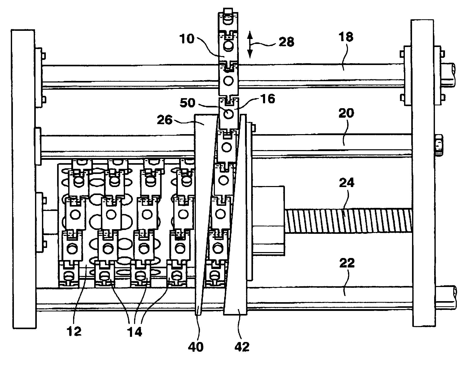
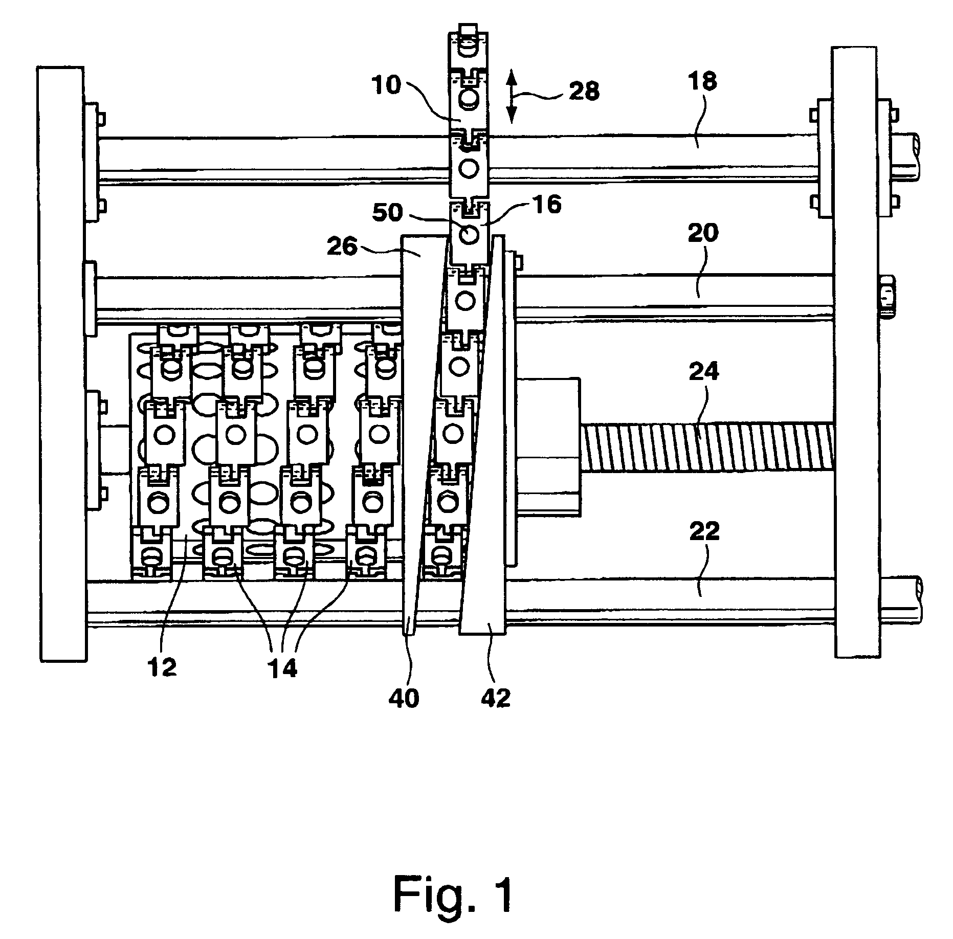
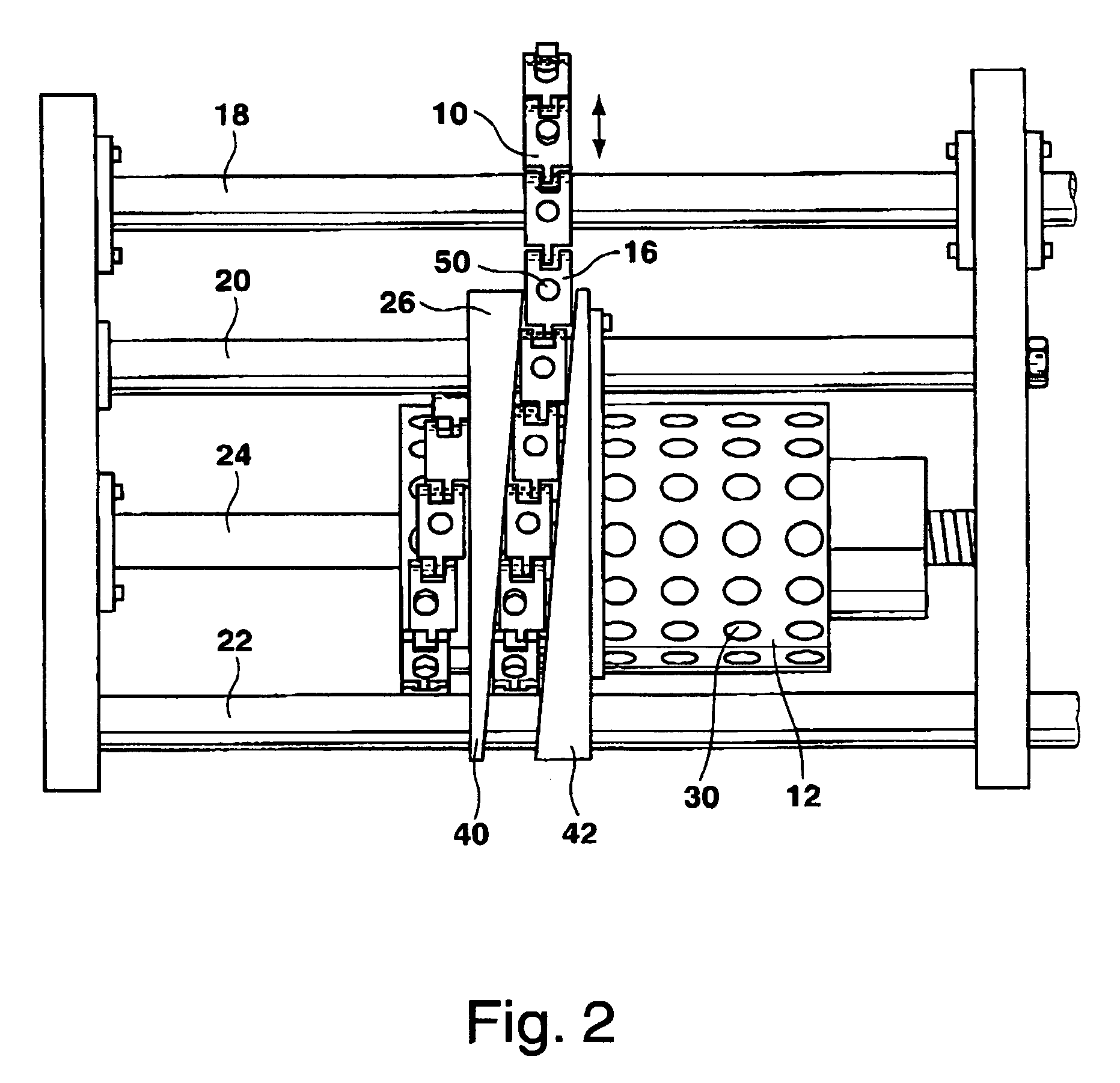
[0022]In the systems for transporting persons or goods from A to B, traction chains 10 are often utilized to drive the transport platform (which has not been illustrated in closer detail herein). The traction chain 10 is thereby stored in a device for storing said traction chain 10. Said device includes a drum 12 about which the traction chain 10 is wound in a plurality of turns 14. The traction chain 10, which is composed of a plurality of links 16, is solidly fixed at its last link to the drum so that the traction chain 10 is prevented from becoming displaced on the drum 12.

[0023]The device for storing the traction chain 10 further includes a drive wheel that has not been illustrated in closer detail herein and that is rotatably carried on a shaft 18, as well as two retaining rods 20, 22, a screw drive 24 and a restraint 26 that has been configured of two parts here.

[0024]The drum 12 is carried on the screw drive 24 in such a manner that the drum 12 is movable pursuant to arrow 28...


PUM


Abstract

The subject matter of the invention is a device and a method for storing a traction chain, more specifically a self-bracing traction chain. Such a device and such a method for storing the traction chain so that is occupies very little space are provided by having the traction chain (10) would into a plurality of side-by-side turns (14) about a winding apparatus (12) carried so as to be rotatable about its longitudinal axis.

Description

CROSS-REFERENCE TO RELATED APPLICATIONS[0001]This application claims Priority from German Application No. DE 20 2004 006 624.6 filed on 26 Apr. 2004BACKGROUND OF THE INVENTION[0002]1. Field of the Invention[0003]The present invention relates to a method of storing a self-bracing traction chain.[0004]2. Description of the Prior Art[0005]In systems for transporting persons or items, traction chains are often utilized to exactly and reliably move the actual transport platform from A to B. They may for example be lifts for persons or loads or feeding machines for feeding objects to processing plants or evacuating them therefrom, said processing plants being for example freeze drying facilities or coating furnaces. It is thereby known from the document DE 44 24 287 C2 or from EP 0 403 576 B1 to store the traction chains before, behind or beneath the actual drive wheel. Because, as a rule, such a traction chain can only be deviated in one direction, it is often stored beneath the drive wh...

Claims


Application Information

Patent Timeline
Patent Type & Authority Patents(United States)
IPC IPC(8): B66D1/30F16G13/07F16G13/18F27B9/14F27D3/04
CPCF16G13/07F27D3/04F27B9/14F16G13/20
Inventor WAGNER, ALEXANDERBATTENBERG, RALF
Owner HOF SONDERANLAGENBAU
Why Eureka
Try Eureka