Pump inlet manifold

a technology of pump inlet and manifold, which is applied in the direction of positive displacement liquid engine, piston pump, liquid fuel engine, etc., can solve the problems of clogging one or more cylinders at their respective inlet passages, excessive wear or damage of certain pump components, and uneven wear on pump components, so as to reduce acceleration pressure losses, minimize fluid pressure losses, and minimize pressure drops

Active Publication Date: 2009-11-24
AHLGREN JASON +1
View PDF17 Cites 22 Cited by
  • Summary
  • Abstract
  • Description
  • Claims
  • Application Information

AI Technical Summary

Benefits of technology

[0007]In accordance with further aspects of the present invention an improved pump inlet manifold is provided wherein fluid velocities are stabilized in the pump inlet piping thereby minimizing pressure drops by preventing the fluid flow from reaching peak pump velocity in the inlet piping. Velocity stabilization in the inlet piping reduces acceleration pressure losses associated with sudden fluid velocity changes in the inlet piping when pump valves open. Acceleration induced pressure variations from pump inlet valve opening and closing is prevented from entering the pump inlet piping. The manifold of the invention also provides one or more guide tubes operable to minimize fluid pressure losses, take advantage of forces which concentrate any entrained solids centrally in the pumped fluid flow stream and provides linear flow into the pump inlet valves.
[0009]Still further, the aforementioned cellular type liner disposed within the manifold provides a solids fluidization mechanism that prevents collecting of solids in the manifold chamber that can restrict fluid flow into the pump chambers. Moreover, the cellular type liner provides rheological mechanisms that reduce the viscosity in the pump inlet manifold of shear thinning fluids to minimize pressure drop throughout the pump inlet ports and inlet valves.

Problems solved by technology

For example, pumps for use in pumping well drilling fluids, slurries of mined ore particulates and slurries of mine tailings require pumping fluids with substantial quantities of solids particulates which should not be allowed to accumulate in the pump manifolding or to be unevenly distributed to the pump cylinders thereby causing excessive wear on or damage to certain pump components.
However, uneven distribution of solids particulates often occurs through the manifold discharge ports and there is a tendency for particulates to drop out of the fluid flowstream and accumulate near one or more of the manifold discharge passages resulting in uneven wear on pump components, such as valving, cylinders and plungers, and possibly clogging one or more cylinders at their respective inlet passages.
In addition, uneven solids distribution and uneven fluid flow produces erratic pump operation which may cause damage, including fatigue failure of valves, crank and wrist pin bearings, connecting rods and crankshafts, for example.

Method used


Image

  • Pump inlet manifold
  • Pump inlet manifold
  • Pump inlet manifold

Examples


Embodiment Construction

[0016]In the description which follows, like parts are marked throughout the specification and drawing with the same reference numbers, respectively. The drawing figures may not be to scale and certain features may be shown in somewhat schematic form or exaggerated in scale in the interest of clarity and conciseness.

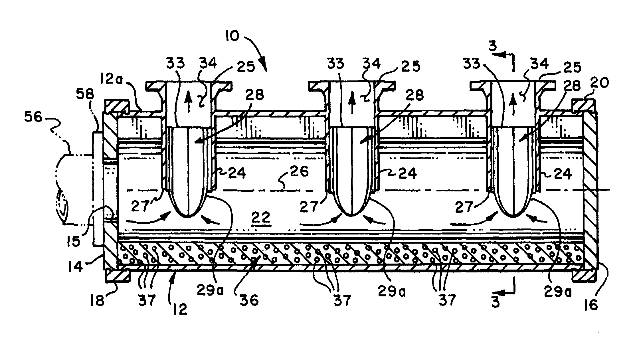
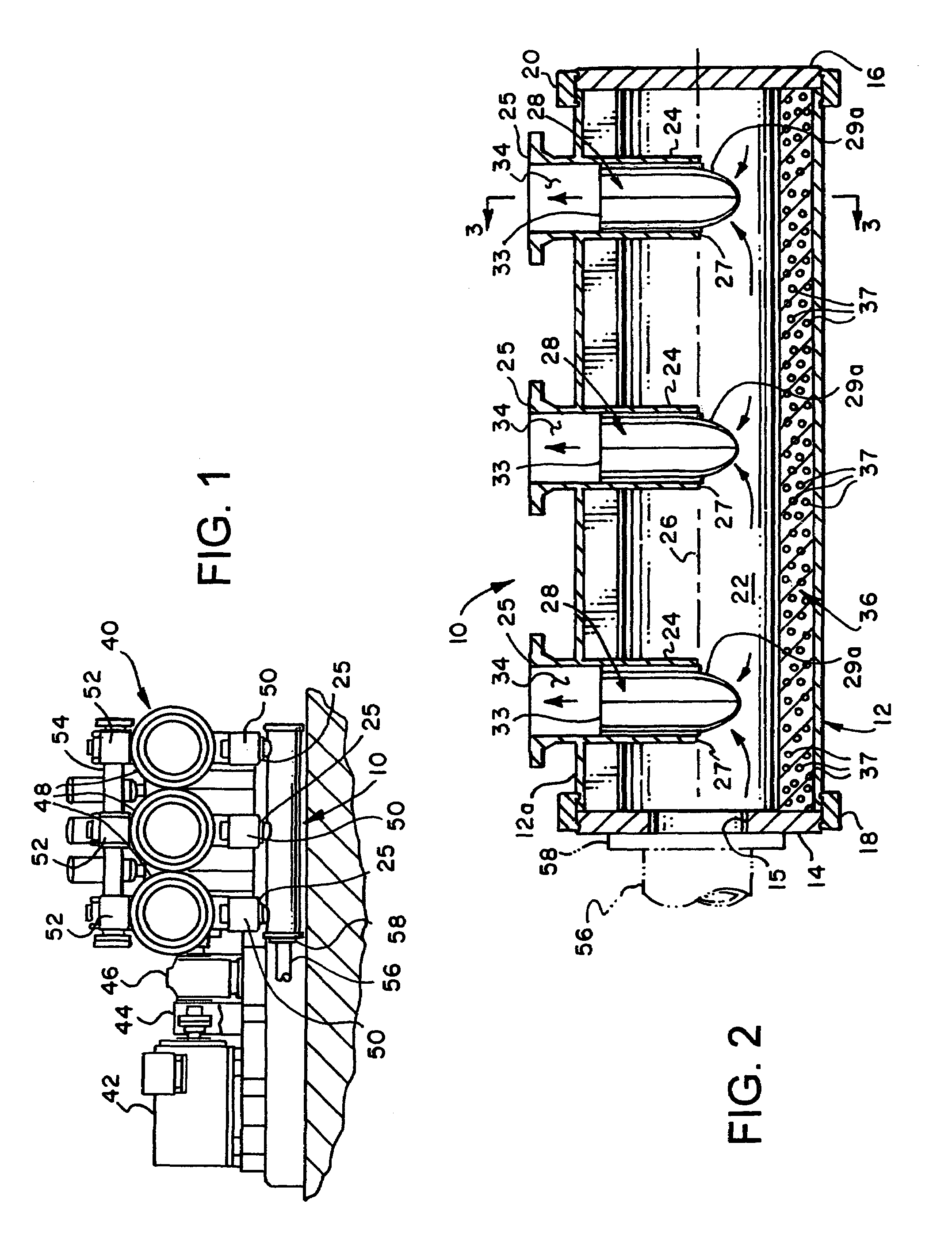
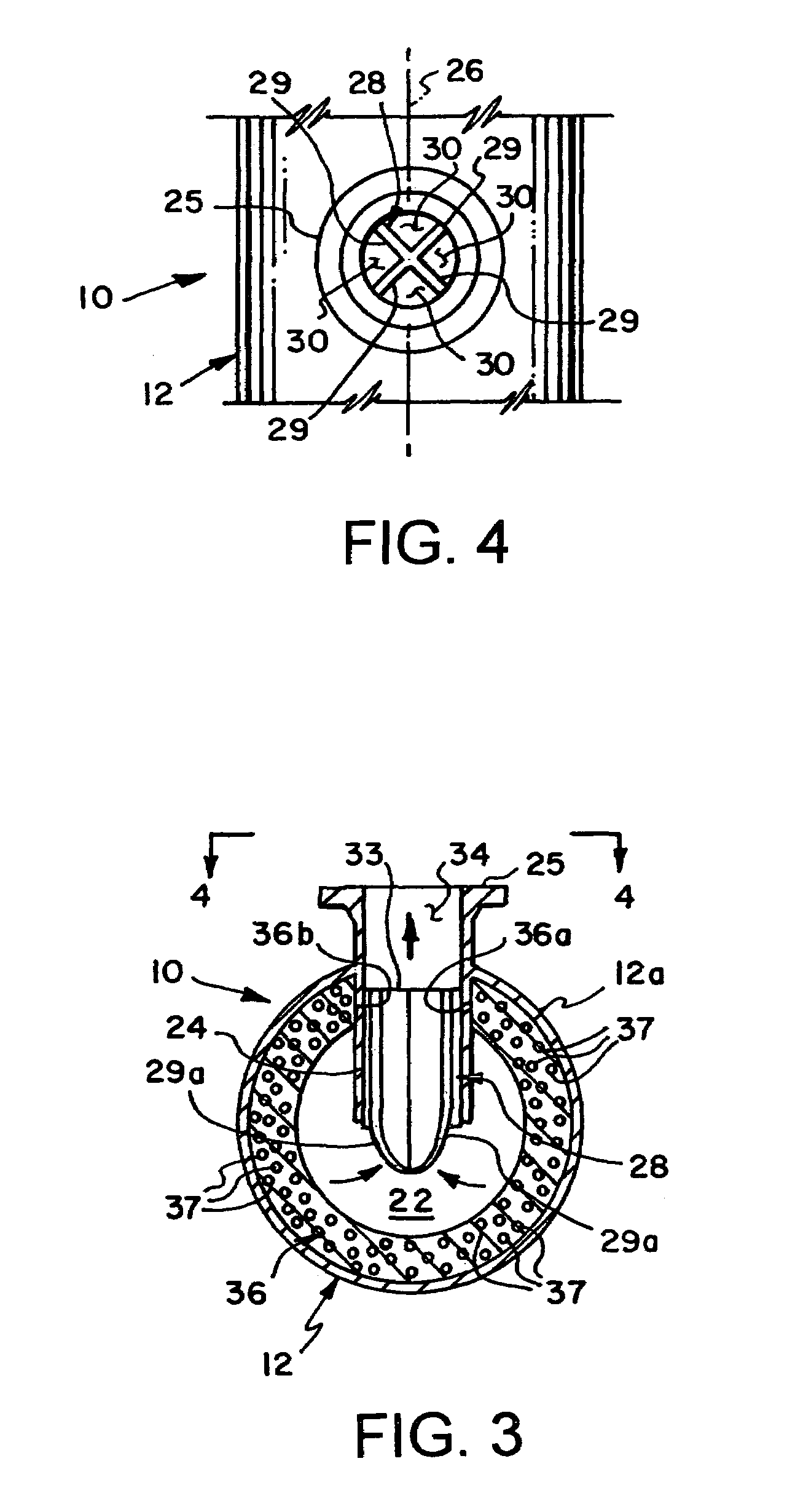
[0017]Referring to FIG. 1, there is illustrated a conventional multicylinder reciprocating plunger pump 40 adapted to be driven by a motor 42 in a conventional manner through a coupling 44 and a speed reduction drive mechanism 46, for example. Pump 40 includes, by way of example, three cylinders 48 forming a so-called triplex plunger pump. Cylinders 48 are each provided with inlet valve housings 50 suitably connected to the cylinders as well as discharge valve housings 52 also suitably connected to the cylinders 48. Discharge valve housings 52 are suitably connected to a fluid discharge manifold 54. As shown in FIG. 1, pump 40 is provided with a fluid inlet manifold 10 i...


PUM


Abstract

A reciprocating piston / plunger pump inlet manifold includes an elongated cylindrical manifold member closable at opposite ends by transverse end caps connected to the manifold member by releasable couplings. A rubber or polymer liner formed with nitrogen filled closed cells is disposed within the manifold member. Spaced apart fluid discharge guide and mixing tubes are connected to the manifold member and include flanges for securing the manifold to inlet valve housings of a pump. The fluid flow guide and mixing tubes include partitions and a mixing chamber portion of the tubes. Improved fluid flow characteristics with minimal solids separation and minimal fluid velocity or acceleration induced pressure losses are exhibited by the manifold.

Description

CROSS REFERENCE TO RELATED APPLICATION[0001]This application claims the benefit of U.S. Provisional Patent Application Ser. No. 60 / 578,687 filed Jun. 10, 2004.BACKGROUND OF THE INVENTION[0002]Many applications for reciprocating piston / plunger pumps require pumping fluids with entrained solids particulates. For example, pumps for use in pumping well drilling fluids, slurries of mined ore particulates and slurries of mine tailings require pumping fluids with substantial quantities of solids particulates which should not be allowed to accumulate in the pump manifolding or to be unevenly distributed to the pump cylinders thereby causing excessive wear on or damage to certain pump components.[0003]Heretofore one pump component that has suffered from accumulations of solids particulates and the uneven distribution of solids particulates in the fluid throughput comprises the pump inlet manifold. In multi-cylinder reciprocating plunger pumps, typically, a pump inlet manifold is connected to...

Claims


Application Information

Patent Timeline
Patent Type & Authority Patents(United States)
IPC IPC(8): F04B39/10F04B53/10F04B17/00F04B35/00F04B53/16
CPCF04B53/16
Inventor MILLER, J. DAVIS
Owner AHLGREN JASON
Why Eureka
Try Eureka