Fine bubble airlift device

a technology of airlift device and airlift device, which is applied in the direction of carburetating air, water cleaning, biological water/sewage treatment, etc., can solve the problems of inefficiency of surface aerators, frequent maintenance of parts, and bubbles of ambient air trapped in water

Inactive Publication Date: 2009-11-24
SWAN HLDG
View PDF13 Cites 28 Cited by
  • Summary
  • Abstract
  • Description
  • Claims
  • Application Information

AI Technical Summary

Problems solved by technology

This causes bubbles of ambient air to become trapped in the water, some of which are absorbed into the water.
Surface aerators are inefficient, requiring a large energy input relative to the volume of water aerated.
They also have several moving parts which can require frequent maintenance.
When the diffuser is submerged in water, the movement of gas through the device causes bubbles to emerge from the pores and into the water.
However, it has been found that dome diffusers are difficult to maintain, lack durability, and are more costly to manufacture in mass production.
However, a key objection to off-the-shelf porous rubber hoses and other porous rubber aeration products is that, after a cure period in water, the hose requires high air pressure delivery systems because the rubber particles unsatisfactorily swell in water thereby decreasing pore diameter.
Decreasing pore diameter causes increased flow resistance and uneven aeration patterns in long runs of tubing become more problematic as the pipes age in their environment.
Further problems associated with the manufacture of porous aeration pipe utilizing previous methods have included irregularly shaped pipe walls, inconsistent porosity, and ineffective micropore size and wall thickness producing inconsistent and unreliable aeration rates.
However, the air bubbles are irregularly distributed throughout the body of the hose, leading to irregular size and placement of the pores.
Additionally, it may take multiple bubbles being linked together to actually form a passage completely through the hose, which increases the resistance of the path.
Both of these conditions can lead to inefficiencies, which can reduce the efficacy of an air lift which employs such a diffuser.
However, for reasons described above, many known devices for diffusing fine air bubbles into water are expensive or inefficient to operate.

Method used


Image

  • Fine bubble airlift device
  • Fine bubble airlift device
  • Fine bubble airlift device

Examples


Embodiment Construction

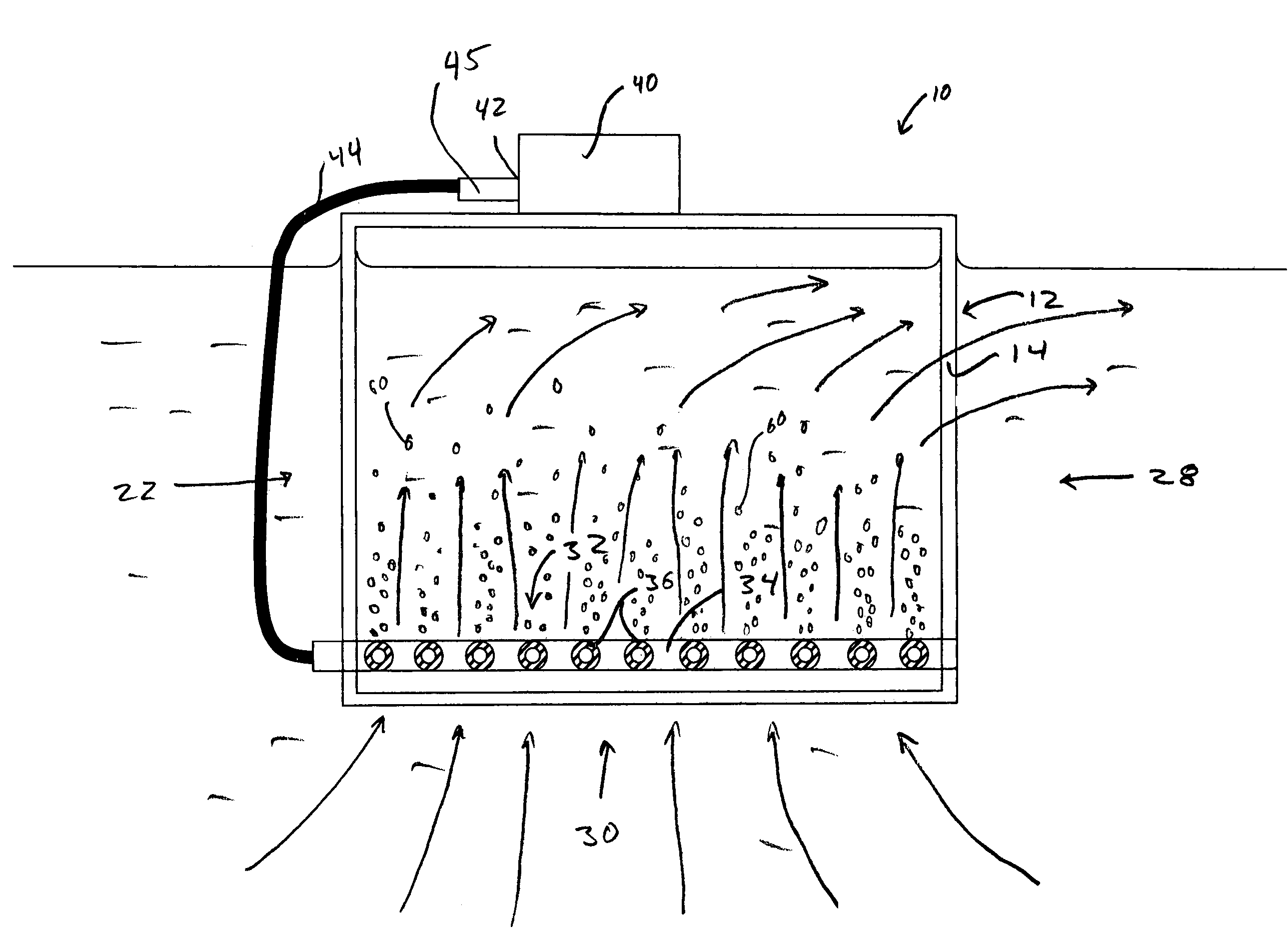
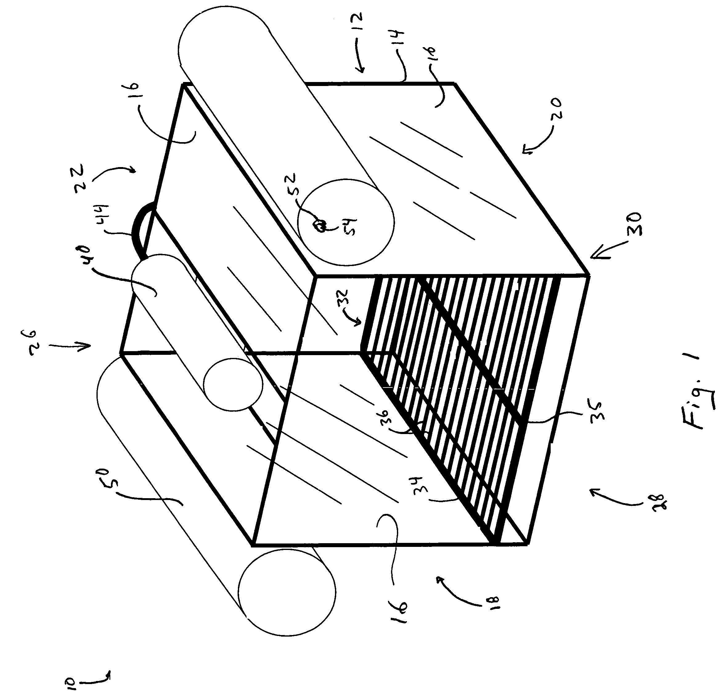
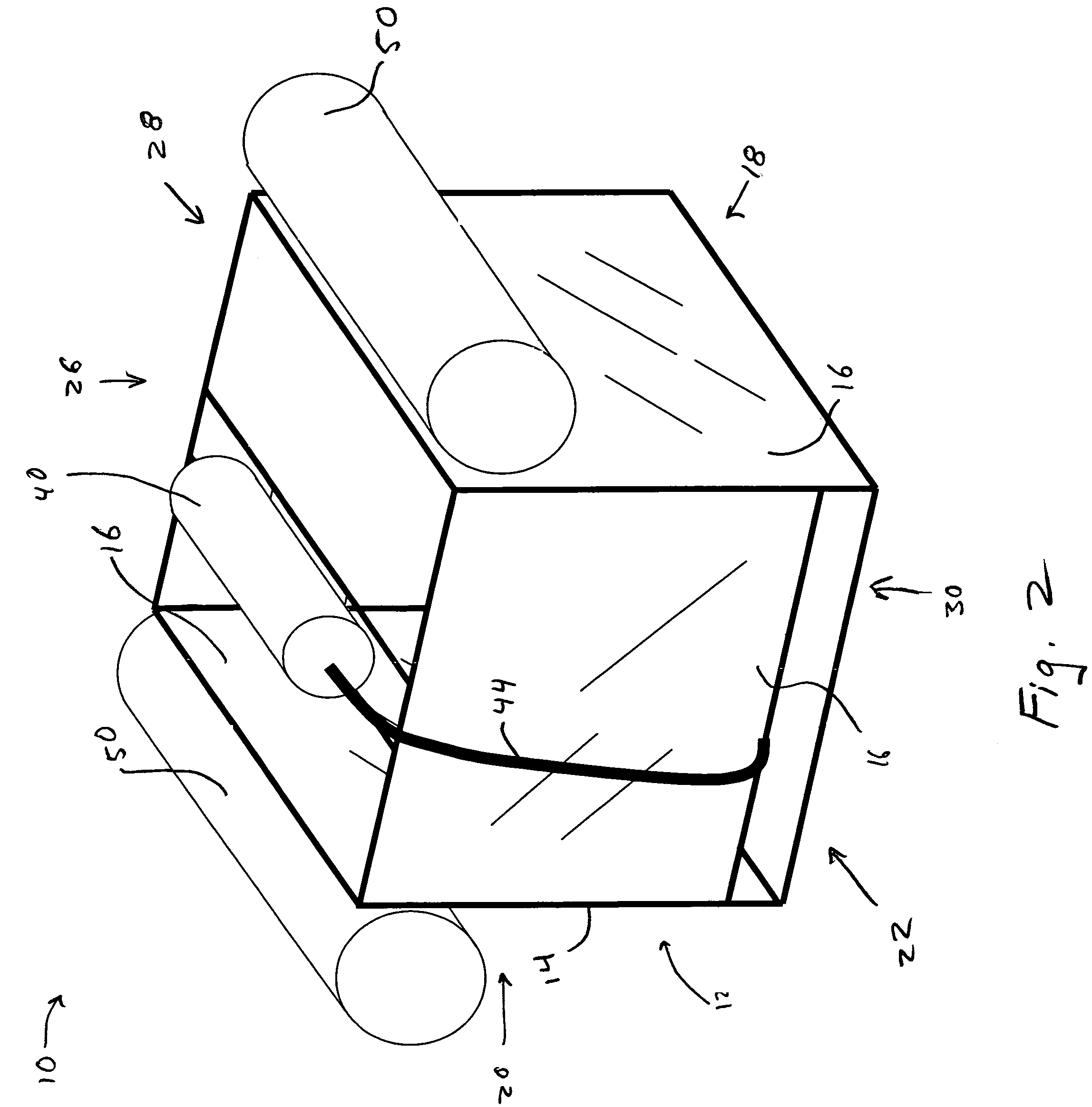
[0020]Referring now to the figures, wherein like reference numerals refer to like features, there is shown in FIG. 1 a device 10 according to an embodiment of the present invention. The device has a housing 12 including a frame 14. Frame 14 may be made of any material that is strong enough to support the weight of the remaining components of the device 10 and will not corrode or otherwise degrade in the presence of water, including salt water or water with waste materials of other chemicals dissolved therein. Preferably, support members are made from marine-grade aluminum or another similar metal. Support members are preferably assembled by welding or other known methods, including the use of screws, bolts, rivets or the like.

[0021]Frame 14 is structured to provide the desired shape for housing 12. The structure of frame 14 shown herein is in the shape of a rectangular prism, although other acceptable shapes for aeration devices, such as cylinders, are possible. The use of these des...


PUM

PropertyMeasurementUnit
diameteraaaaaaaaaa
diameteraaaaaaaaaa
porosityaaaaaaaaaa

Abstract

The present invention relates to an aeration device for use in a liquid medium. The device includes a housing adapted to float within the medium such that a top portion thereof remains above a top surface of the medium. The housing has a bottom portion and an open side portion. The device further includes a hose affixed to the bottom portion of the housing substantially parallel to the surface of the liquid medium. The hose has a wall with a plurality of pores formed therein. The device further includes a gas-supplying pipe affixed to the hose and means for supplying a gas to the pipe such that the gas passes through the pipe and into the hose.

Description

BACKGROUND OF THE INVENTION[0001]The present invention relates to an apparatus for aerating and circulating a liquid and, in particular, water in a pond.[0002]Various devices exist for the introduction of air bubbles into a mass of liquid, typically water. Such devices have numerous applications which encompass areas such as aquaculture, including culturing and raising fish in controlled environments (known generally as fish farming), waste water management and the like. Other uses are generally known in the art. Such devices include what are generally known as surface aeration devices and air lift devices.[0003]Surface aeration devices in the art use a form of paddle wheel to agitate the water near the surface thereof. This causes bubbles of ambient air to become trapped in the water, some of which are absorbed into the water. The paddles further force the aerated water away from the device and draw additional water toward the device to be aerated. Surface aerators are inefficient,...

Claims


Application Information

Patent Timeline
Patent Type & Authority Patents(United States)
IPC IPC(8): E02B15/04B01F3/04C02F1/74
CPCB01F3/04262B01F13/0049B01F3/0412C02F3/223C02F7/00A01K63/042C02F3/201B01F2003/04319B01F2003/0439Y02W10/10B01F23/2311B01F23/23123B01F23/231265B01F33/503
Inventor MITCHELL, WILLIAM S.SCHMIDT, ROLANDJOHNSON, ROY TRENCE
Owner SWAN HLDG
Why Eureka
Try Eureka