Al technical title is built by PatSnap Al team. It summarizes the technical point description of the patent document.
a technology of electrophoresis cartridge and interface mechanism, which is applied in the field of bioseparation, can solve the problems of time-consuming and expensive existing dna analysis procedures
Active Publication Date: 2009-11-24
QIAGEN SCIENCES LLC
View PDF8 Cites 20 Cited by
Summary
Abstract
Description
Claims
Application Information
AI Technical Summary
This helps you quickly interpret patents by identifying the three key elements:
Problems solved by technology
Method used
Benefits of technology
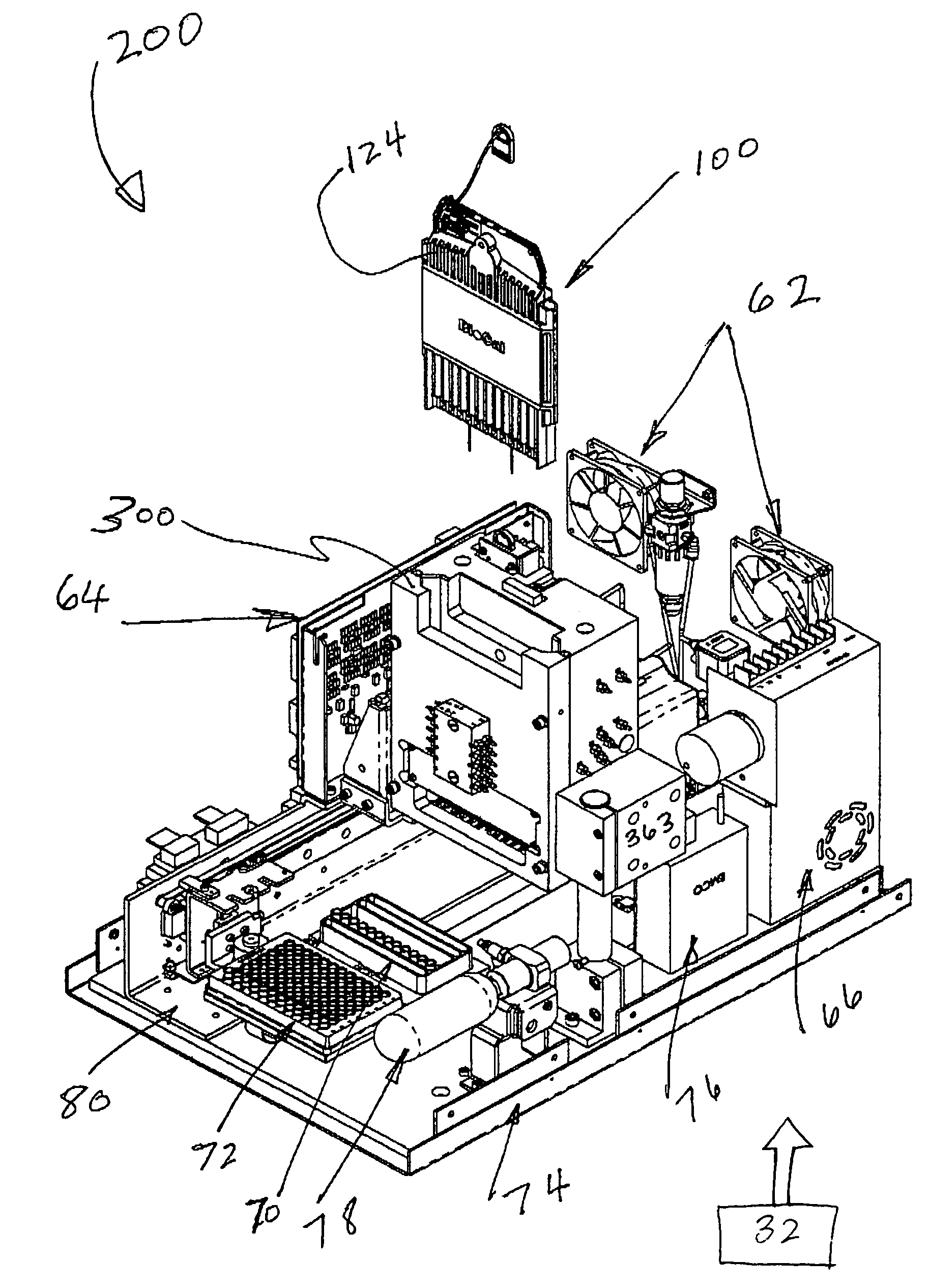
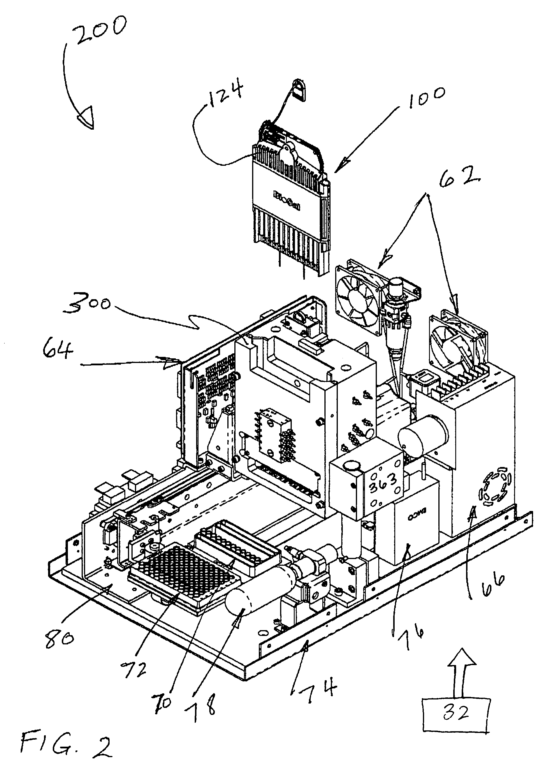
[0009]The present invention provides for an interface mechanism in a bio-separation instrument that makes interface connections to a multi-channel cartridge. One aspect of the present invention provides an interface mechanism that precisely positions the cartridge in relation to the support elements (e.g., electrical power such as high-voltage, gas pressure, incident radiation and detection optics) provided by the supporting instrument, and makes automated, reliable and secured alignments and connections between various components in the cartridge and the support elements in the instrument. Such alignments and connections are reliably implemented, in a reliable automated sequence, after the cartridge had been securely received by the interface mechanism.
Problems solved by technology
Yet due to the complexity of the equipment that detects and measures DNA samples and the difficulty in preparing the samples, the existing DNA analysis procedures are often time-consuming and expensive.
Some of the challenges in designing CE-based instruments relate to the support of the capillaries and alignment of the capillaries to support elements (e.g., excitation and detection optics).
Method used
Image
Click on the blue label to locate the original text in one second.
Reading with bidirectional positioning of images and text.
Examples
Embodiment Construction
[0044]This invention is described below in reference to various embodiments with reference to the figures. While this invention is described in terms of the best mode for achieving this invention's objectives, it will be appreciated by those skilled in the art that variations may be accomplished in view of these teachings without deviating from the spirit or scope of the invention.
[0045]The present invention provides for an interface mechanism bio-separation instrument that supports a multi-segment cartridge. For purpose of illustrating the principles of the present invention and not by limitation, the present invention is described by reference to embodiments directed to capillary electrophoresis and radiation induced fluorescence.
Overview of CE
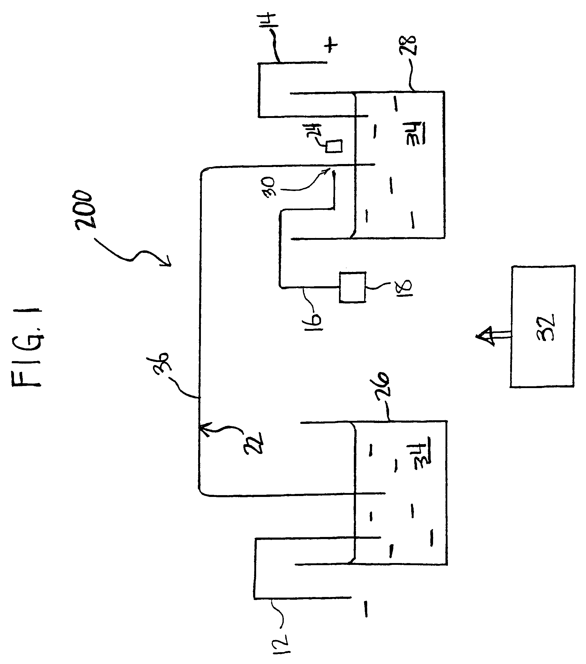
[0046]Referring to FIG. 1, a bio-separation system, more specifically a capillary electrophoresis (CE) system 200 that incorporates the present invention is schematically illustrated. The CE system 200 generally comprises a capillary separat...
PUM
Property
Measurement
Unit
thick
aaaaa
aaaaa
wavelength
aaaaa
aaaaa
wavelength
aaaaa
aaaaa
Abstract
The present invention provides for an interface mechanism in a bio-separation instrument that makes interface connections to a multi-channel cartridge. The interface mechanism precisely positions the cartridge in relation to the support elements in the instrument (e.g., high-voltage, gas pressure, incident radiation and detector), and makes automated, reliable and secured alignments and connections between various components in the cartridge and the support elements in the supporting instrument. The interface mechanism comprises pneumatically or electromechanically driven actuators for engaging support elements in the instrument to components on the cartridge. After the cartridge has been securely received by the interface mechanism, the connection sequence is initiated. The interface provides separate high voltage and optical connections for each separation channel in the cartridge, thus providing channel-to-channel isolation from cross talk both electrically and optically.
Description
[0001]This application claims the priority of U.S. Provisional Patent Application No. 60 / 462,481, filed on Apr. 11, 2003.[0002]This application is a Continuation-in-Part of U.S. patent application Ser. No. 10 / 059,993 entitled “Multi-Channel Bio-Separation Cartridge,” filed on Jan. 28, 2002 now U.S. Pat. No. 7,309,409; and U.S. patent application Ser. No. 10 / 060,052, entitled “Optical Detection In A Multi-Channel Bio-Separation System”, filed on Jan. 28, 2002 now U.S. Pat. No. 6,828,567; and U.S. patent application Ser. No. 10 / 319,803, entitled “Optical Detection Alignment Coupling Apparatus”, filed on Dec. 13, 2002 now U.S. Pat. No. 7,250,099; and PCT Application No. PCT / US03 / 39971, entitled “Optical Detection Alignment Coupling Apparatus”, filed on Dec. 15, 2003; which are commonly assigned to BioCal Technology, Inc., the assignee of the present invention.[0003]The above-mentioned applications, and all other applications, documents and references noted in the disclosure herein belo...
Claims
Application Information
Patent Timeline
Application Date:The date an application was filed.
Publication Date:The date a patent or application was officially published.
First Publication Date:The earliest publication date of a patent with the same application number.
Issue Date:Publication date of the patent grant document.
PCT Entry Date:The Entry date of PCT National Phase.
Estimated Expiry Date:The statutory expiry date of a patent right according to the Patent Law, and it is the longest term of protection that the patent right can achieve without the termination of the patent right due to other reasons(Term extension factor has been taken into account ).
Invalid Date:Actual expiry date is based on effective date or publication date of legal transaction data of invalid patent.