
Contamination monitoring and control techniques for use with an optical metrology instrument

a technology of optical metrology and contamination monitoring, applied in the field of optical metrology, can solve the problems of reducing the performance of optical instruments, challenging the sensitivity of such instruments, and contamination of optical surfaces like windows and mirrors, so as to eliminate the build-up

Active Publication Date: 2009-11-24
BRUKER TECH LTD
View PDF38 Cites 2 Cited by
  • Summary
  • Abstract
  • Description
  • Claims
  • Application Information

AI Technical Summary

Benefits of technology

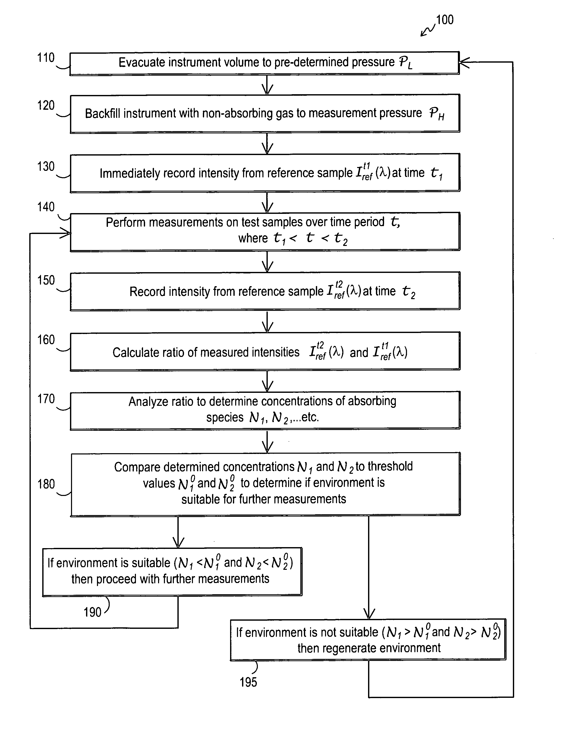
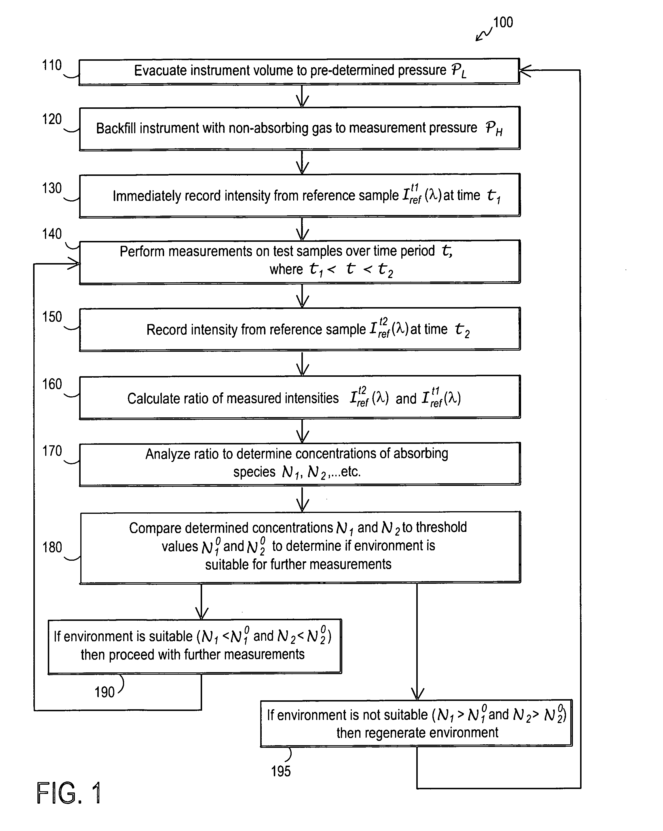
[0010]One embodiment of the disclosed techniques provides a technique for generating and subsequently monitoring the controlled environment(s) within a VUV optical metrology instrument in such a manner as to minimize, or all together eliminate, the build-up of contaminants on the surfaces of optical elements that may result in performance degradation.
[0011]Another embodiment discloses a technique for reducing surface contaminants from optical elements contained within the optical path (or sub-path) of an optical metrology instrument. The technique may be utilized in one embodiment in such a manner as to not require that additional components and / or instrumentation be coupled to, or integrated into, existing metrology equipment.
[0012]Another embodiment discloses a technique whereby surface contaminants on optical elements within an optical metrology instrument are monitored so that cleaning procedures can be performed as deemed necessary. The technique may further enable separate optical paths of the instrument to be monitored, and subsequently cleaned, independent of one another.
[0013]In yet another embodiment, a technique is disclosed for removing contaminants from the surface of a sample prior to recording an optical response from said sample in order to ensure that accurate results are obtained. In one alternative, the technique may be implemented in such a manner as to not require that additional components and / or instrumentation be coupled to, or integrated into, existing metrology equipment.
[0015]In another embodiment, a method of controlling an atmosphere in an optical metrology tool is provided. The method may include providing at least a first environmentally controlled chamber and a second environmentally controlled chamber, the first and second environmentally controlled chambers configured for passage of a light beam having wavelengths below DUV wavelengths. The method may further include lowering the concentration of an optical absorbing species in at least one of the first and second environmentally controlled chambers by utilizing vacuum evacuation techniques, the at least one of the first and second environmentally controlled chambers being a controlled atmosphere chamber. Further the method may include backfilling, with a non-absorbing gas, the controlled atmosphere chamber so as to improve optical performance by increasing a pressure within the controlled atmosphere chamber above a vacuum evacuation pressure level and transmitting the light beam having wavelengths below DUV wavelengths while the controlled atmosphere chamber is in the backfilled state.
[0017]In another embodiment a method of controlling an atmosphere in an optical metrology tool may include providing at least an environmentally controlled sample chamber and an environmentally controlled optics chamber, the sample chamber and optics chamber each being configured for passage of a light beam having wavelengths below DUV wavelengths. The method may further include providing a sample beam optical path and a reference beam optical path, the optical path lengths of the sample beam optical path and the reference beam optical patch being matched. The method also may include decreasing from an ambient state the concentration of moisture or oxygen in at least one of the sample chamber and the optics chamber by utilizing vacuum evacuation techniques, the at least one of the sample chamber and the optics chamber in which the decreasing occurs being a controlled atmosphere chamber. The method may further include backfilling, with a VUV non-absorbing gas, the controlled atmosphere chamber so as to improve the optical performance by increasing a pressure within the controlled atmosphere chamber above a vacuum evacuation pressure level and transmitting the light beam having wavelengths below DUV wavelengths while the controlled atmosphere chamber is in the backfilled state.

Problems solved by technology

The continuous push towards developing smaller devices comprised of thinner layers has challenged the sensitivity of such instrumentation.
Contamination of optical surfaces like windows and mirrors is a serious impediment to the operation of optical instruments in the VUV.
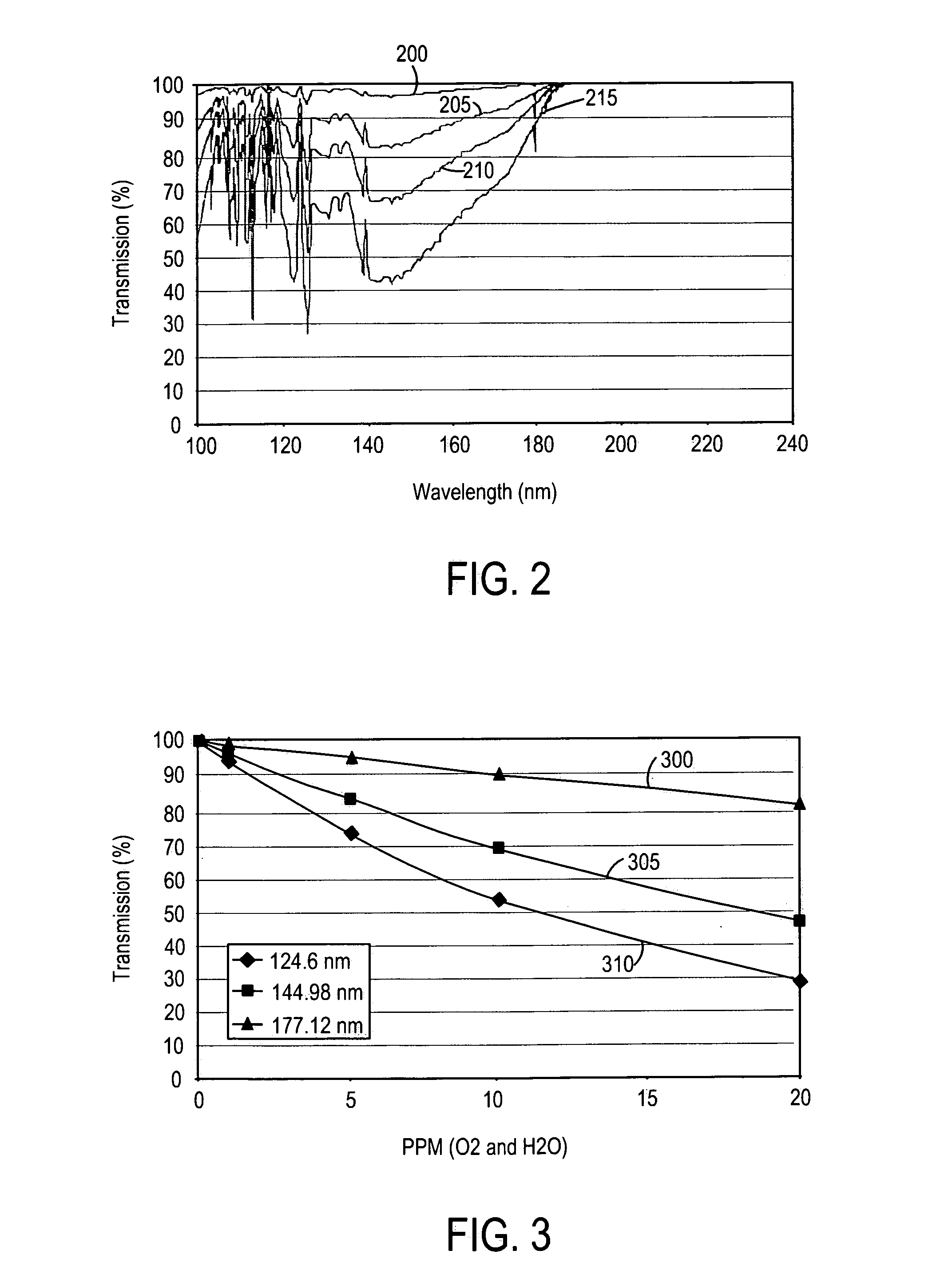
Moisture and residual molecules, particularly hydrocarbon compounds, may deposit on such surfaces over time dramatically reducing their performance.
When present on the surfaces of samples under investigation, contaminate layers may significantly contribute to measured optical responses in the VUV yielding inaccurate and / or erroneous results.
Although enhanced measurement repeatability is reported using this approach, the method requires that a separate cleaning system be coupled to an existing measurement system resulting in increased system cost and design complexity.

Method used


Image

  • Contamination monitoring and control techniques for use with an optical metrology instrument
  • Contamination monitoring and control techniques for use with an optical metrology instrument
  • Contamination monitoring and control techniques for use with an optical metrology instrument

Examples


Embodiment Construction

[0037]To enhance the sensitivity of optical metrology equipment for challenging applications it is desirable to extend the range of wavelengths over which such measurements are performed. Specifically, it is advantageous to utilize shorter wavelength (higher energy) photons extending into, and beyond, the region of the electromagnetic spectrum referred to as the vacuum ultra-violet (VUV). Vacuum ultra-violet (VUV) wavelengths are generally considered to be wavelengths less than deep ultra-violet (DUV) wavelengths, i.e. less than about 190 nm. While there is no universal cutoff for the bottom end of the VUV range, some in the field may consider VUV to terminate and an extreme ultra-violet (EUV) range to begin (for example some may define wavelengths less than 100 nm as EUV). Though the principles described herein may be applicable to wavelengths above 100 nm, such principles are generally also applicable to wavelengths below 100 nm. Thus, as used herein it will be recognized that the...


PUM


Abstract

A technique is provided for generating and subsequently monitoring the controlled environment(s) within an optical metrology instrument in such a manner as to minimize absorbing species within the light path of the metrology instrument and to minimize the build-up of contaminants on the surfaces of optical elements that may result in performance degradation. Both evacuation and backfill techniques may be utilized together along with a monitoring technique to determine if the environmental is suitable for measurements or if the environment should be regenerated. The optical metrology instrument may be an instrument which operates at wavelengths that include vacuum ultra-violet (VUV) wavelengths.

Description

RELATED APPLICATIONS[0001]The present application claims priority to U.S. Provisional Patent Application No. 60 / 795,467 filed Apr. 27, 2006, the disclosure of which is expressly incorporated herein by reference. The present application also expressly incorporates by reference the following two U.S. patent applications concurrently filed on the same date as the present application: U.S. patent application Ser. No. 11 / 600,414, entitled CONTAMINATION MONITORING AND CONTROL TECHNIQUES FOR USE WITH AN OPTICAL METROLOGY INSTRUMENT by Harrison and Weldon; and U.S. patent application Ser. No. 11 / 600,477, entitled CONTAMINATION MONITORING AND CONTROL TECHNIQUES FOR USE WITH AN OPTICAL METROLOGY INSTRUMENT by Harrison and Weldon.BACKGROUND OF THE INVENTION[0002]The present application relates to the field of optical metrology and more particularly to optical metrology that may be performed in the vacuum ultraviolet (VUV).[0003]In one embodiment, a means by which accurate and repeatable optica...

Claims


Application Information

Patent Timeline
Patent Type & Authority Patents(United States)
IPC IPC(8): H01L21/66
CPCG01J3/02G01J3/0232G01J3/0291G01J3/42G01N21/33G01J3/08G01N21/94
Inventor HARRISON, DALE A.WELDON, MATTHEW
Owner BRUKER TECH LTD
Learn More