Liquid crystal display device

a display device and liquid crystal technology, applied in static indicating devices, non-linear optics, instruments, etc., can solve the problems of deteriorating contrast, inconvenient display of moving pictures such as tv images, and insufficient reduction of transmittance in black display conditions

Inactive Publication Date: 2009-11-24
JAPAN DISPLAY CENTRAL CO LTD
View PDF9 Cites 118 Cited by
  • Summary
  • Abstract
  • Description
  • Claims
  • Application Information

AI Technical Summary

Benefits of technology

[0041]The present invention can control for example a tinge of blue of the displayed image in the black display of the display screen in the OCB mode liquid crystal display.
[0042]The OCB mode display relating to the present invention is to control the phase of passing light upon combining the liquid crystal display cell with the phase difference plate and varying the summation of retardation values thereof, and represented by the following:Re=(ne−no)d=Δn·d  (1),
[0043]where the retardation value of the liquid crystal display cell is represented by Re.
[0044]Here, ‘no’ denotes ordinary index; ‘ne’ denotes extraordinary index; and ‘d’ denotes thickness of the liquid crystal layer. The OCB liquid crystal layer employing p type liquid crystal having positive dielectric anisotropy has a positive retardation value, and the phase difference plate combined with the liquid crystal layer above has a negative retardation value.
[0045]As shown in FIG. 19, when the liquid crystal display panel is composed of the liquid crystal display cell 11, the phase difference plate 20 and a pair of the polarization plates 22 arranged in the crossed-Nicol configuration to each other, light transmittance (T) is represented as follows:(T)∝ sin 2(Ret(V,λ) / λ)  (2),where Ret denotes summation of retardation values of the liquid crystal layer and the phase difference plate; V denotes voltage supplied to the liquid crystal layer; and λ denotes wavelength of the light.
[0046]FIG. 13 shows an example of Δnd / λ to the wavelength λ in the liquid crystal layer used for the OCB mode display. Because the value increases as the wavelength becomes shorter, it is difficult to control it even if a phase difference plate having a similar tendency is combined therewith. Therefore, light leakage due to light dispersion of short wavelength light is liable to increase.

Problems solved by technology

Although the TN type liquid crystal display device can be manufactured comparatively easily, it is not suitable to display moving pictures such as TV images because the viewing angle is narrow and the response speed is slow.
As a result, when observation is carried out from the direction normal to the substrate (the front direction of the display screen), the transmittance in the black display condition cannot be sufficiently decreased, so that the above phenomenon gives rise to deterioration of the contrast.

Method used


Image

  • Liquid crystal display device
  • Liquid crystal display device
  • Liquid crystal display device

Examples


embodiment 1

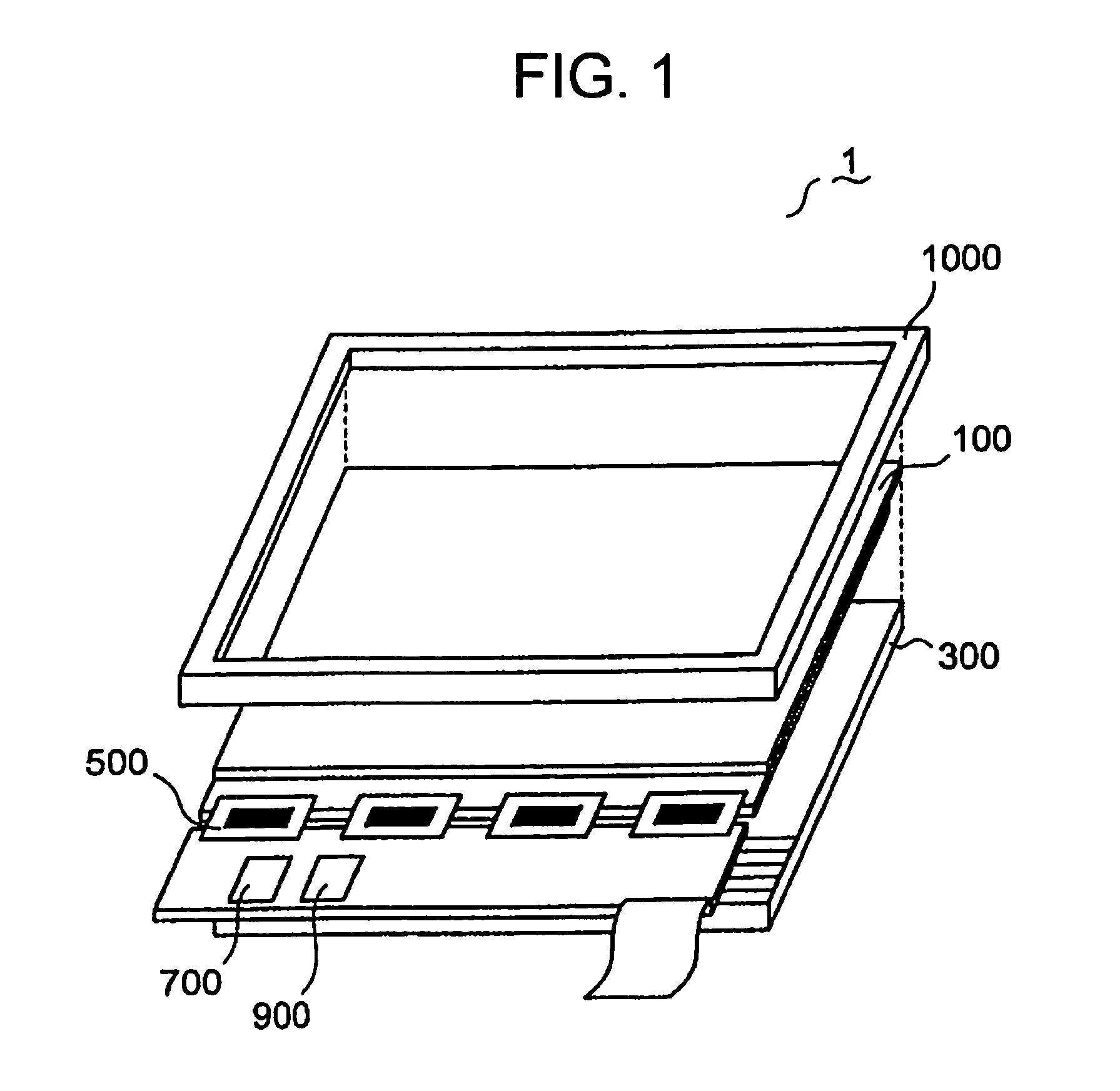
[0058]FIG. 1 shows a schematic block diagram of the liquid crystal display device according to the OCB mode system of the embodiment.

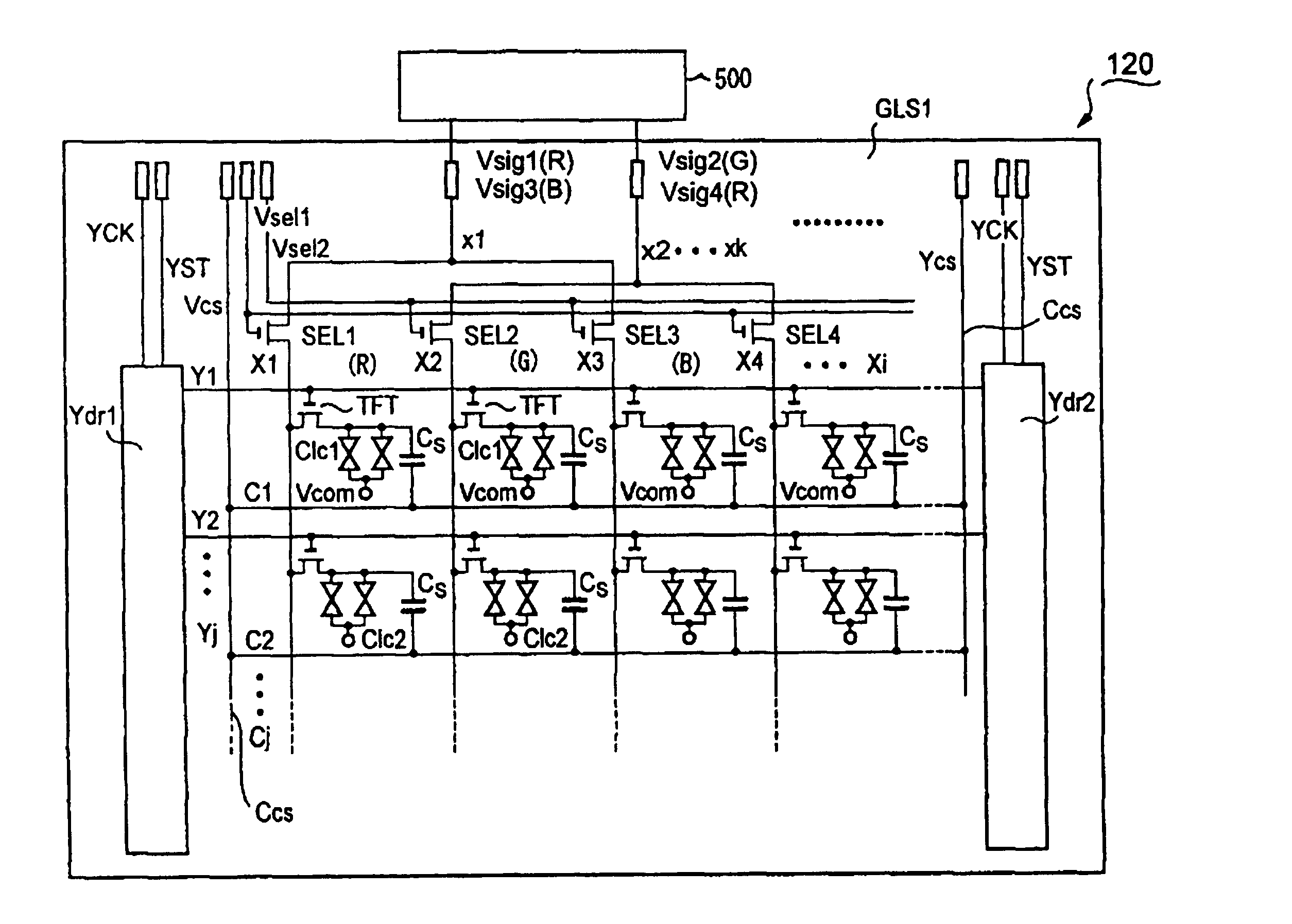
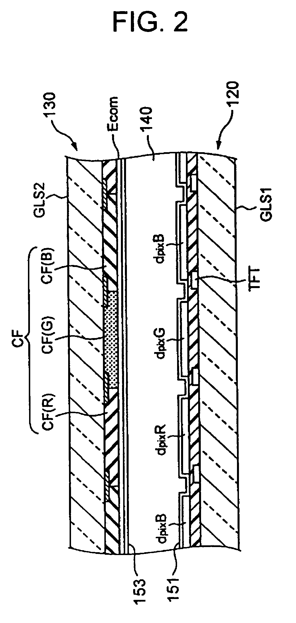
[0059]The liquid crystal display device 1 having the aspect ratio of 16:9 and the diagonal of 22 inches comprises a liquid crystal display panel 100 of light transmission active matrix type, a backlight 300 constituted of a plurality of tubular light sources 310 arranged in parallel together (Refer to FIG. 11) and located at the back of the liquid crystal display panel, scanning line drive circuits Ydr1, Ydr2 (Refer to FIG. 4) accommodated in the liquid crystal display panel 100 and supplying a scan signal Vg to a scanning line Yj, a signal line drive circuit 500 comprised of TCP (Tape Carrier Package) supplying a signal voltage Vsig to a signal line Xi (Refer to FIG. 4), an opposing electrode drive circuit 700 supplying an opposing electrode voltage Vcom to an opposing electrode Ecom (Refer to FIG. 2), and a control circuit 900 controlling the scannin...


PUM

PropertyMeasurementUnit
wavelengthaaaaaaaaaa
voltageaaaaaaaaaa
wavelengthaaaaaaaaaa

Abstract

It is possible to eliminate the blue tone in the black color display in the OCB liquid crystal display device. A liquid crystal display cell (110) includes an opposing substrate (130) having an opposing electrode (Ecom), an array substrate (120) having pixel electrodes of the respective colors (dpixR, dpixG, dpixB), a liquid crystal layer (140) arranged in a bend-arrangement and sandwiched between the opposing substrate (130) and the array substrate (120), and red, green, and blue filter layers (CF(R), CF(G), CF(B)) arranged on one of the substrates. The maximum voltage is applied when performing black color display on the display screen. At least the maximum voltage of the pixel electrode for blue color dpixB applied to the opposing electrode (Ecom) is made different from the maximum voltage of the pixel electrodes of the other colors applied to the opposing electrode (Ecom).

Description

TECHNICAL FIELD[0001]The present invention relates to a liquid crystal display device, and more particularly to a liquid crystal display device employing the optically compensated birefringence (OCB) technology enabling realization of a wide viewing angle and high speed response.TECHNICAL BACKGROUND[0002]Liquid crystal display devices are put in practical use in various application fields with taking advantage of the characteristics thereof such as lightweight, a thin outline, and less power consumption.[0003]Twisted nematic (TN) type liquid crystal display devices now widely utilized in the market have a structure in which liquid crystal material thereof having optically positive refractive index anisotropy is arranged between the substrates in such a manner as to be twisted by approximately 90 degrees, so that optical rotatory property of the incident light is regulated upon controlling the twisted alignment. Although the TN type liquid crystal display device can be manufactured c...

Claims


Application Information

Patent Timeline
Patent Type & Authority Patents(United States)
IPC IPC(8): G02F1/133G02F1/1335G02F1/1337G02F1/139G09G3/36
CPCG02F1/1395G09G3/3651G02F1/133514G09G2300/08G09G2300/0491G09G3/3614G02F1/133
Inventor ARAKI, SHIGESUMINISHIYAMA, KAZUHIROOKITA, MITSUTAKASUZUKI, DAIICHI
Owner JAPAN DISPLAY CENTRAL CO LTD
Why Eureka
Try Eureka