
Image processing method, apparatus and program

a technology of image processing and apparatus, applied in the field of image processing methods and apparatus, can solve the problems of long processing time, inability to obtain satisfactory results, and inability to achieve satisfactory results, and achieve the effect of excellent tonal reproduction

Inactive Publication Date: 2009-11-24
FUJIFILM CORP
View PDF8 Cites 7 Cited by
  • Summary
  • Abstract
  • Description
  • Claims
  • Application Information

AI Technical Summary

Benefits of technology

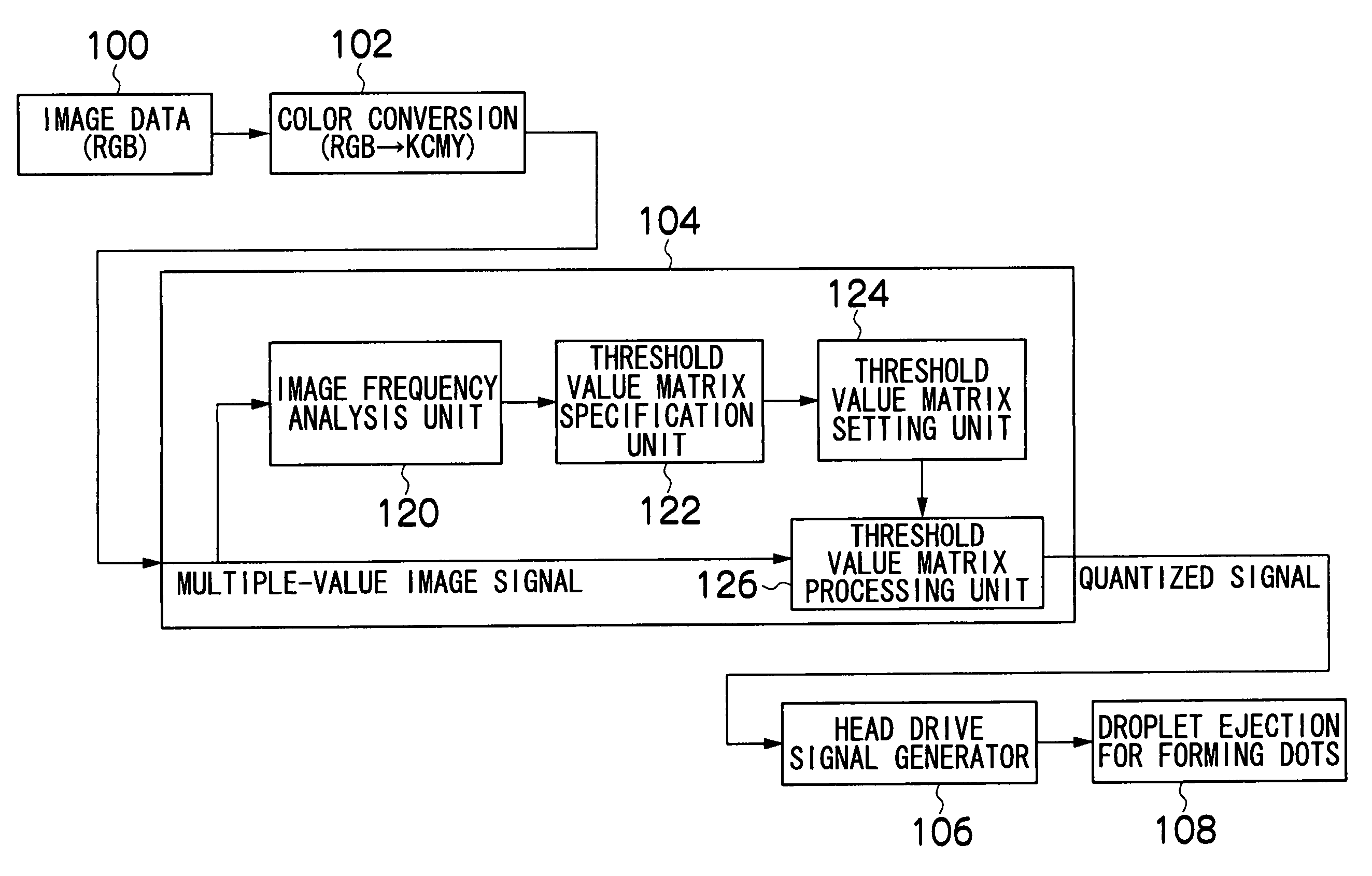
This approach enables the production of a quantized image that effectively responds to sudden changes in image characteristics while maintaining desirable tonal reproduction, reducing processing time by optimizing matrix size and arrangement for each image block.

Problems solved by technology

For example, if an error diffusion matrix or a threshold value matrix having a broad range of distribution is used, then it is possible to reproduce portions of the image having a smooth variation in density distribution, in a satisfactory manner, but in portions where the density distribution changes suddenly, the response declines and such satisfactory results cannot be obtained.
Furthermore, a long processing time is required, since a large number of multiply and accumulation operations are made.
If the image is quantized by changing between different threshold value matrices within one image in this way, then a problem arises in that the processing may not necessarily appropriate for an image in which the spatial frequency characteristics change within a region, for instance, if there is a sudden change in density within region 412.

Method used


Image

  • Image processing method, apparatus and program
  • Image processing method, apparatus and program
  • Image processing method, apparatus and program

Examples


first embodiment

[0151]FIGS. 9A to 9C show threshold value matrices which are used in the aforementioned binarization processing. The high-frequency threshold value matrix 200 shown in FIG. 9A is a threshold value matrix having a size of m×m, which is used when the spatial frequency of the block under examination is a high frequency. Moreover, the medium-frequency threshold value matrix 202 shown in FIG. 9B is a threshold value matrix having a size of (2×m)×(2×m), which is used when the spatial frequency of the block under examination is a medium frequency. Furthermore, the low-frequency threshold value matrix 204 shown in FIG. 9C is a threshold value matrix having a size of (4×m)×(4×m), which is used when the spatial frequency of the block under examination is a low frequency.

[0152]The medium-frequency threshold value matrix 202 and the low-frequency threshold value matrix 204 shown in FIGS. 9B and 9C can be divided into sub-matrices by taking the size of the high-frequency threshold value matrix 2...

second embodiment

[0183]Next, a second embodiment of the present invention will be described.

[0184]In the present embodiment, in addition to a threshold value matrix as illustrated in the first embodiment described above, suitable threshold value matrices are used in accordance with changes in spatial frequency characteristics in the respective oblique directions, leftwards, rightwards, upwards and downwards. FIGS. 14A to 14C show threshold value matrices according to the second embodiment.

[0185]FIG. 14A shows a H / L threshold value matrix 240 used for an image block in which the spatial frequency changes from low-frequency to high-frequency; FIG. 14B shows a M / L threshold value matrix 242 used for an image block in which the spatial frequency changes from low-frequency to medium-frequency; and FIG. 14C shows a M / H threshold value matrix 244 used for an image block in which the spatial frequency changes from medium-frequency to high-frequency.

[0186]The H / L threshold value matrix 240, the M / L threshold...


PUM


Abstract

The image processing method for obtaining a quantized image from a multiple tone image, the method comprises: an image dividing step of dividing an input image into a plurality of image blocks of a unit block size; a threshold value matrix specification step of specifying threshold value matrices for the input image with respect to each of the image blocks from a plurality of threshold value matrices including a first threshold value matrix having the unit block size and a second threshold value matrix dividable into a plurality of sub-matrices each having the unit block size; and a threshold value matrix setting step of setting threshold value matrices in image blocks for which the second threshold value matrix has been specified as the threshold value matrix, in such a manner that adjacent positional relationships between sub-matrices formed when the second threshold value matrix is divided into sub-matrix units are preserved.

Description

BACKGROUND OF THE INVENTION[0001]1. Field of the Invention[0002]The present invention relates to an image processing method and apparatus, and to a program for realizing image processing functions in a computer, and more particularly, to quantization processing technology for a multiple-value image suitable for an inkjet recording apparatus or other image forming apparatus.[0003]2. Description of the Related Art[0004]In general, in an inkjet recording apparatus, a graded tonal image is formed by converting the light and shade of the image into an appropriate dot pattern, by using a half-toning method, such as error diffusion, dithering, or the like.[0005]Here, a half-toning process relating to the prior art will be described. The most widely used techniques in half-toning are error diffusion and dithering.[0006]Error diffusion is a method based on processing the errors generated when each dot (pixel) of a multiple-value image is quantized, and reflecting and diffusing these errors i...

Claims


Application Information

Patent Timeline
Patent Type & Authority Patents(United States)
IPC IPC(8): G06K15/00B41J2/01G06K9/36G06T5/00H04N1/40H04N1/405
CPCH04N1/405
Inventor YAMAZAKI, YOSHIROU
Owner FUJIFILM CORP
Learn More