Refrigeration condensate line assembly

a condensate line and refrigeration technology, applied in lighting and heating apparatus, heating types, instruments, etc., can solve problems such as considerable damage, and achieve the effect of enhancing the sensor function and increasing the electrical conductivity of water

Inactive Publication Date: 2009-12-01
COOGLE GREGORY
View PDF12 Cites 22 Cited by
  • Summary
  • Abstract
  • Description
  • Claims
  • Application Information

AI Technical Summary

Benefits of technology

[0009]6. A two-electrode water sensor that can activate a signal when water in a plugged drain line rises enough to wet the electrod

Problems solved by technology

Because water may stand still in the system, various microorganisms may grow in the tray and drain pipe until they clog up the drainage system.
When this occurs, overflowi

Method used


Image

  • Refrigeration condensate line assembly
  • Refrigeration condensate line assembly
  • Refrigeration condensate line assembly

Examples


Embodiment Construction

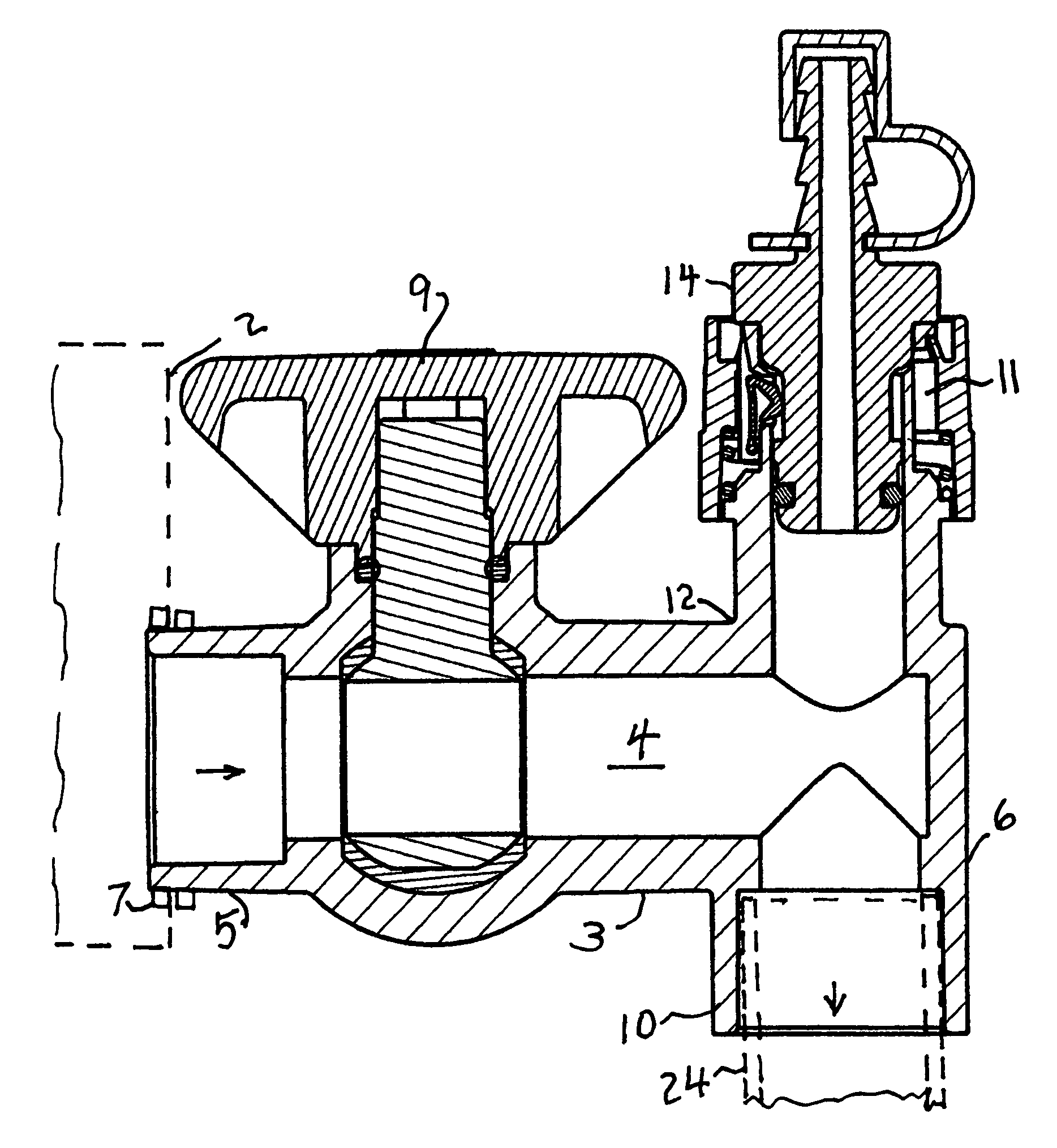
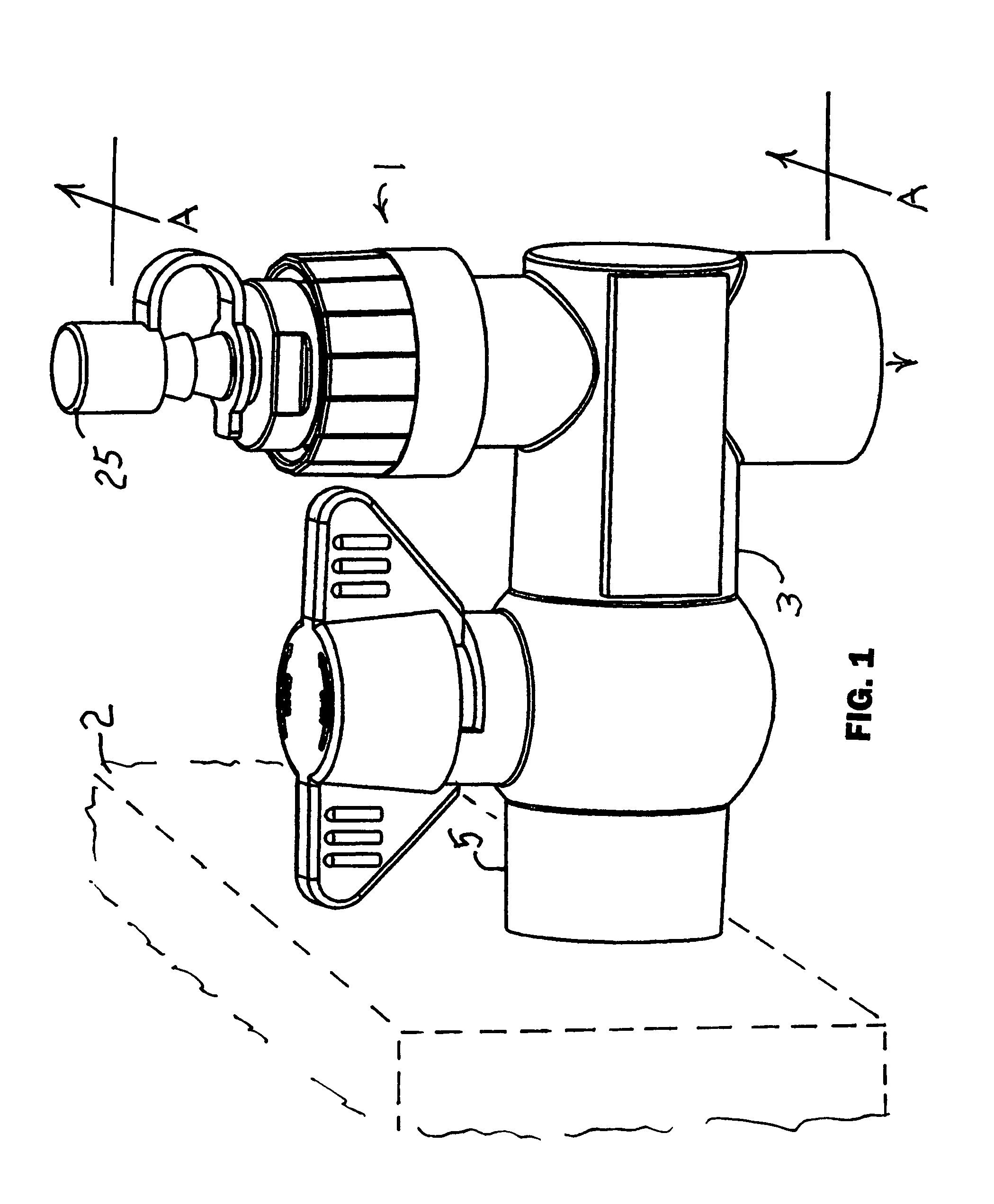
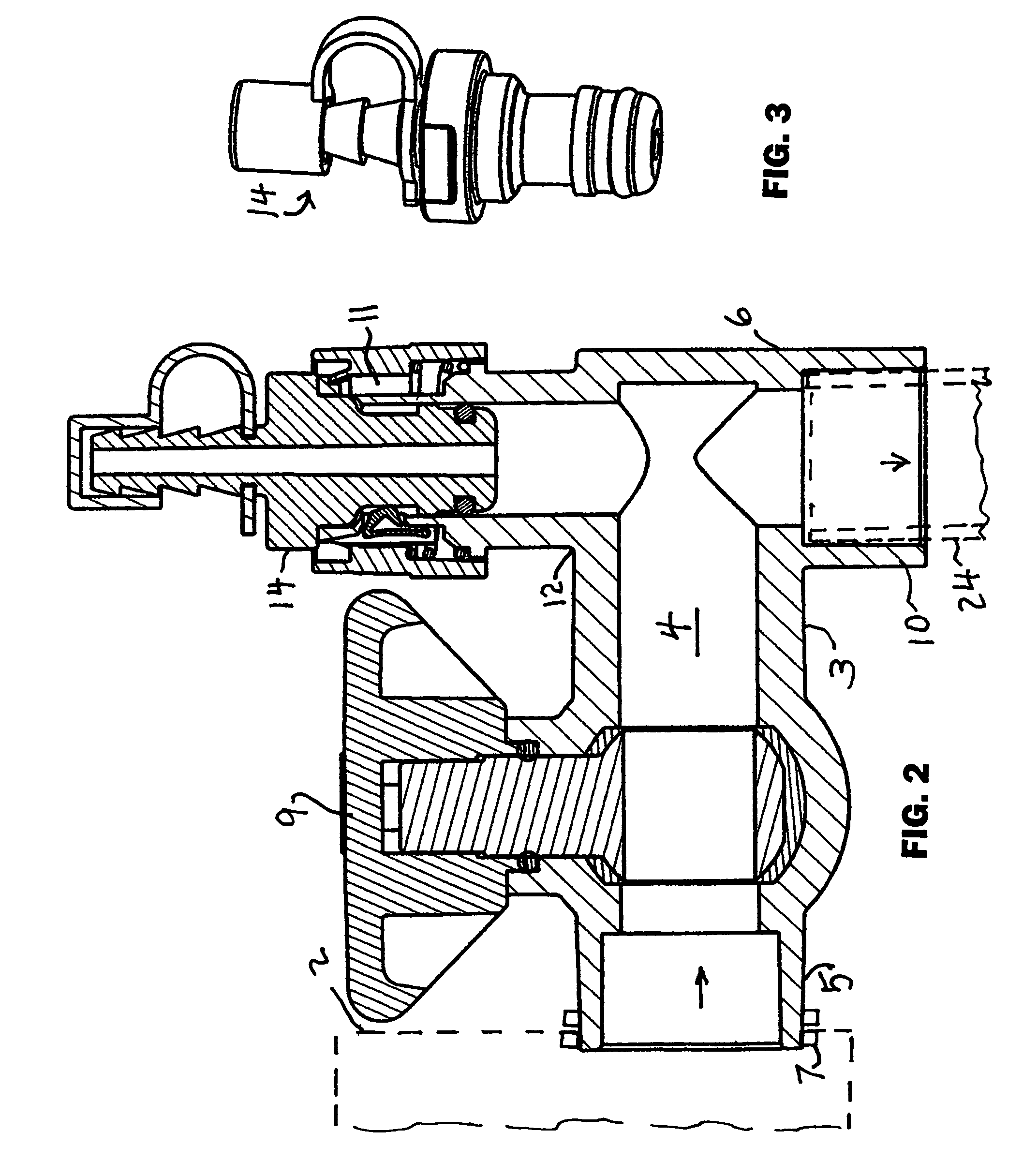
[0021]Referring now first to the drawing FIGS. 1-8, an assembly 1 of the invention includes a housing 3 that has an internal passage 4 with a first end 5 having a first end connector 7 for sealingly connecting to the vertical wall of a condensate pan 2 (shown in phantom). The condensate pan is the type located beneath the coils of a refrigeration evaporator such as found in air conditioning apparatus. Water in air passing over the cooling coils condenses out of the air as it cools. That water condenses on the coils and drips down and collects in the pan. Water in the pan is continuously drained to the outside through a drain pipe 24 (shown in phantom). Debris, often due to microorganism growth, may clog up the drain line. That may cause the drain pan to overflow, causing water damage. Cleaning a clogged drain line may be labor intensive and costly, in addition to the water overflow damage.

[0022]The assembly 1 of the invention is introduced in the drainage system by interposing it be...


PUM


Abstract

An assembly mounts between the drain pan that collects condensate water from an air conditioner and the drain line. It includes a housing with a first end connected to the pan. A second end connects to the drain line. A shut off valve shuts off the passage to the pan while maintenance is performed. A connector is mounted on the housing between the valve and the second end. It is a female member of a quick-connect coupling. A male member of the coupling may be plugged in with a single motion to seal it in place. Male members have different terminations, including a barbed tube for resilient tubing, a compressed air tire valve for delivering gas, a female water hose coupling, a tapered funnel for the nozzle of vacuum/blower, and a water sensor.

Description

FIELD OF THE INVENTION[0001]This invention relates generally to air conditioning apparatus and more particularly to apparatus for maintenance of the water line that drains water from a pan that receives water that condenses on the evaporator coils of an air conditioning system.BACKGROUND OF THE INVENTION[0002]It is well known in the art to provide a receptacle such as a tray or pan beneath the evaporator coils of an air conditioner to receive water that condenses from the air as it is cooled. A drain line is generally connected to a side wall of the tray to drain the condensate water as it accumulates. Because water may stand still in the system, various microorganisms may grow in the tray and drain pipe until they clog up the drainage system. When this occurs, overflowing water may cause considerable damage. Because the drainage system and tray are out of sight and may be relatively inaccessible, they may be neglected until damage occurs. Clearing obstructions in the drain line and...

Claims


Application Information

Patent Timeline
IPC IPC(8): F16L37/00G05D7/00
CPCF24F13/222F28F17/005F24F2013/227Y10T137/4259Y10T137/5283Y10T137/701Y10T137/8342
Inventor COOGLE, GREGORY
Owner COOGLE GREGORY
Why Eureka
Try Eureka