Modular energy absorber with ribbed wall structure

a technology of energy absorber and ribbed wall, which is applied in the direction of shock absorber, elastic damper, bumper, etc., can solve the problems of reducing the cost of components, product cycle time, raw material thickness, and ultimately the cost of components when compared, and achieves cost-effective effects

Inactive Publication Date: 2009-12-01
OAKWOOD ENERGY MANAGEMENT
View PDF20 Cites 39 Cited by
  • Summary
  • Abstract
  • Description
  • Claims
  • Application Information

AI Technical Summary

Benefits of technology

[0008]One object of the present invention is to provide a more cost effective, efficient energy absorber that can be “customized” or “tuned” to produce predefined energy absorption characteristics within spatial constraints (e.g., between a bumper beam and fascia) that may be imposed by a particular application.
[0010]Therefore, in instances where the efficiency of the absorber is less important than the amount of energy absorbed, the disclosed design decreases the raw material thickness, product cycle time, component mass, and ultimately the cost of the component when compared to previous approaches.
[0011]The properties of this innovation are especially well suited for bumper systems, where increasing the amount of energy absorbed and minimizing intrusion tend to be more important than the response curve of the impacted absorber.
[0012]The invention relates to structures that increase the yield point of an absorber and thus protect an underlying component (e.g., a bumper beam) from damage. One embodiment deploys “female” ribs in the side walls of a frustoconical (in one example) structure to prevent it from yielding under a given load.

Problems solved by technology

Therefore, in instances where the efficiency of the absorber is less important than the amount of energy absorbed, the disclosed design decreases the raw material thickness, product cycle time, component mass, and ultimately the cost of the component when compared to previous approaches.

Method used


Image

  • Modular energy absorber with ribbed wall structure
  • Modular energy absorber with ribbed wall structure
  • Modular energy absorber with ribbed wall structure

Examples


Embodiment Construction

)

1. The Energy Absorber

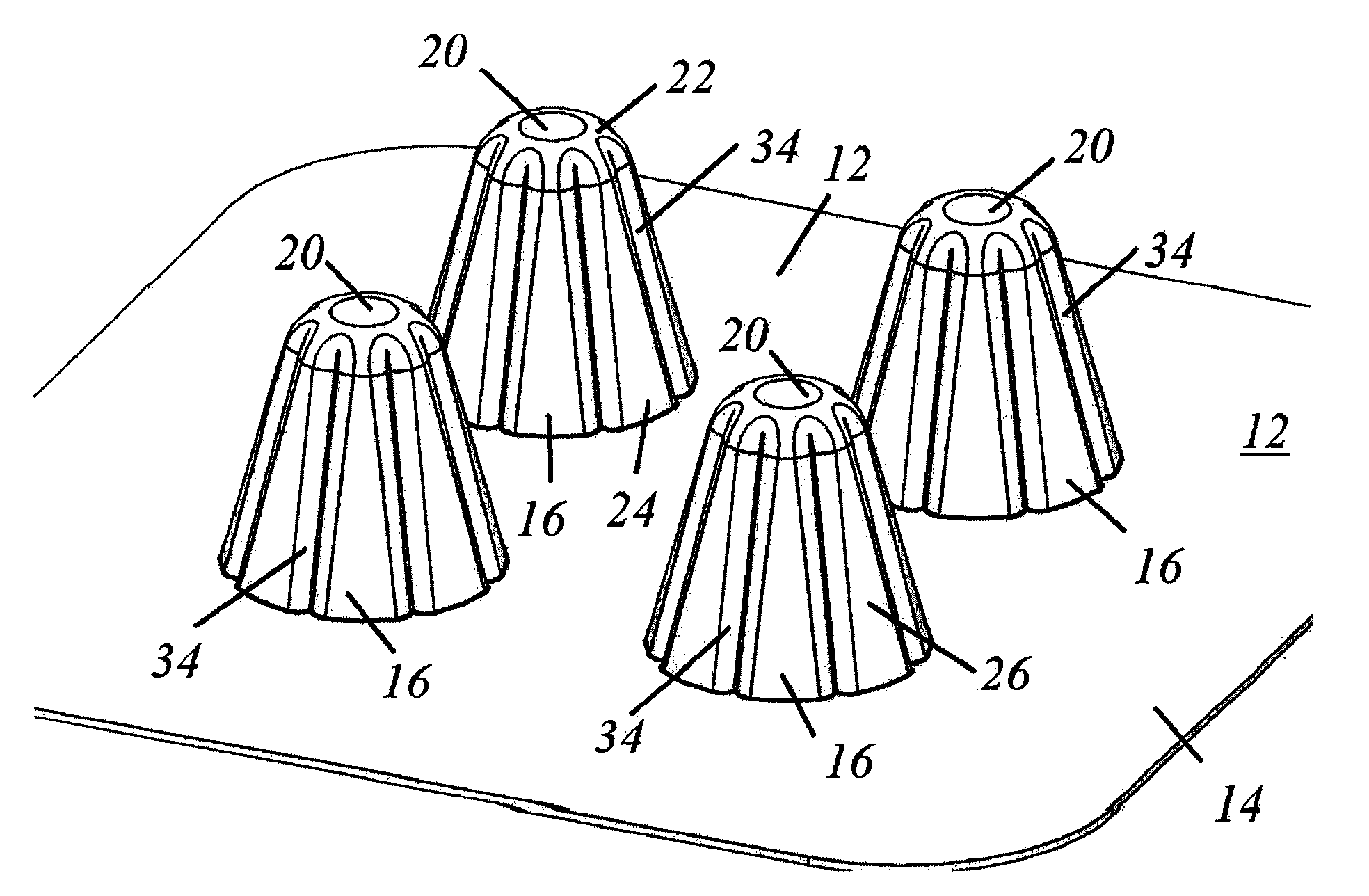
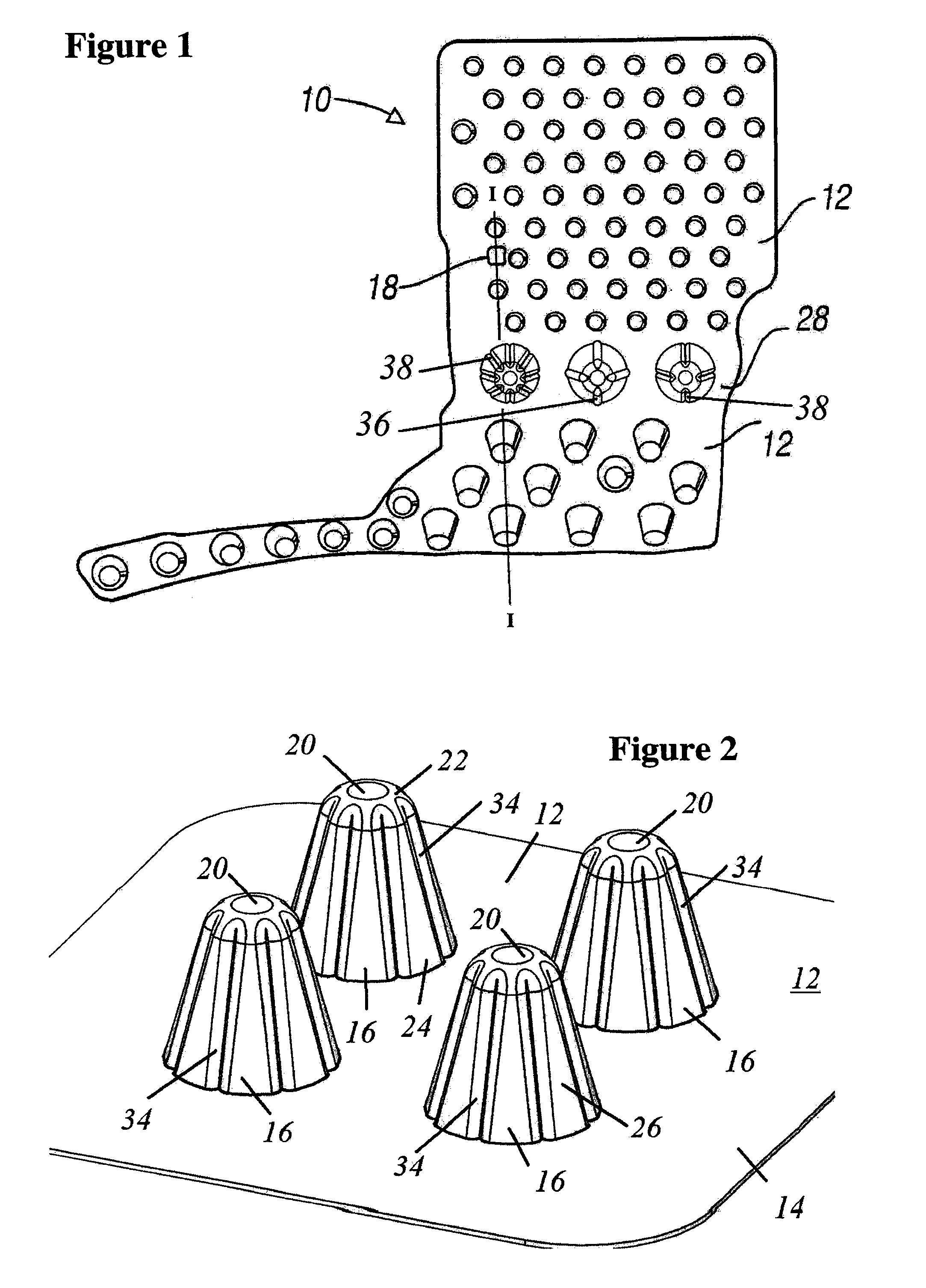
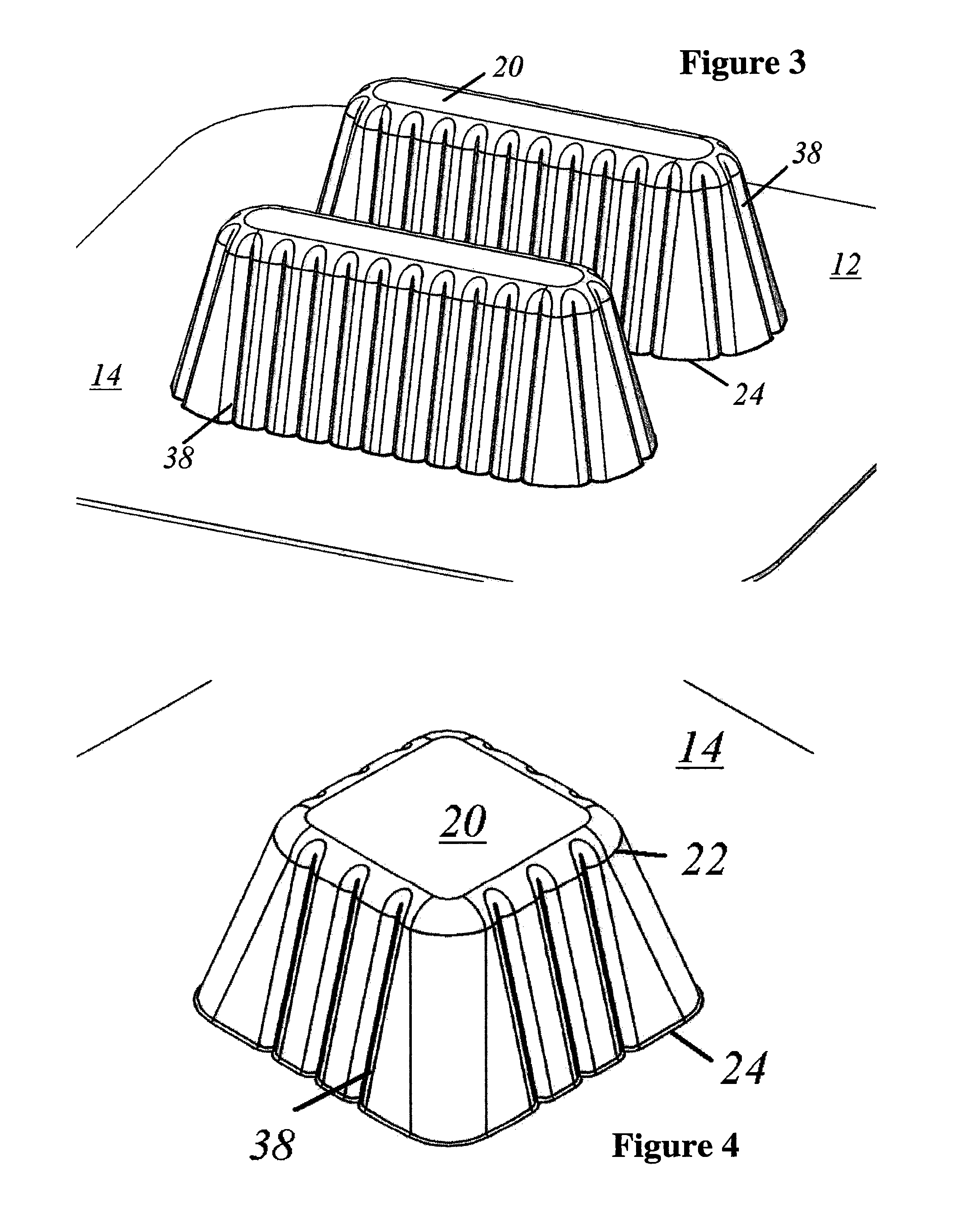
[0029]Turning first to FIG. 1 of the drawings, there is depicted a modular energy absorber or assembly 10 that has one or more (e.g., three in the embodiment depicted) energy absorbing modules 12. The definition of the “energy absorbing module” which appears in the summary section of this application is incorporated here by reference.

[0030]At least some of the one or more modules comprising the assembly include means 14, such as a basal structure, for coordinating energy absorbing units 16 (“absorbers”) of a given energy absorbing module 12. The units are further characterized by one or more male 36 (e.g., FIG. 5) or female ribs 38 (e.g., FIGS. 1, 3) in the walls of the units 16, and by certain shapes, dimensions, and wall thicknesses that can be customized or “tuned” using non-linear finite element analysis software to model a desired energy absorber. Additional options for “tuning” a given energy absorbing module is the provision in a given module of energy ...


PUM

PropertyMeasurementUnit
thicknessaaaaaaaaaa
energyaaaaaaaaaa
impact forcesaaaaaaaaaa

Abstract

A modular energy absorber 10 that is tunable. It comprises one or more energy absorbing modules 12. The energy absorbing modules 12 have means for coordinating 14 energy absorbing units 16 of the one or more modules. The means 14 for coordinating position and support the units 16 in relation to each other before and during relative motion between an incident object and the energy absorber. The units 16 are provided with an upper perimeter 22, a lower perimeter 24 and an intermediate wall 26 with stiffening male 36 or female 38 ribs. A method for configuring and for making the modular energy absorber are also disclosed.

Description

CROSS-REFERENCE TO RELATED APPLICATIONS[0001]This application is a continuation-in-part of U.S. application Ser. No. 11 / 014,418 filed Dec. 16, 2004 now U.S. Pat. No. 7,404,593, which is a continuation-in-part of U.S. application Ser. No. 10 / 760,760 filed Jan. 20, 2004 now U.S. Pat. No. 7,360,822, which is a continuation of U.S. application Ser. No. 10 / 004,739 filed Dec. 4, 2001 (now U.S. Pat. No. 6,752,450), which is a continuation-in-part of U.S. application Ser. No. 09 / 884,813 filed Jun. 19, 2001 (now U.S. Pat. No. 6,682,128) which is a continuation-in-part of U.S. application Ser. No. 09 / 499,205 filed Feb. 7, 2000 (now U.S. Pat. No. 6,247,745). Application Ser. No. 10 / 760,760 is also a continuation-in-part of U.S. application Ser. No. 09 / 617,691 filed Jul. 17, 2000 (now U.S. Pat. No. 6,679,967). All applications in this paragraph are incorporated by reference herein.BACKGROUND OF THE INVENTION[0002]1. Field of the Invention[0003]This invention generally relates to vehicle protect...

Claims


Application Information

Patent Timeline
Patent Type & Authority Patents(United States)
IPC IPC(8): B60R19/26A62B1/22B29C51/10B29C51/12B29C51/14B32B3/28B60N2/42B60N2/70B60R19/18B60R19/34B60R21/04B65D81/127F16F1/376F16F7/12
CPCA62B1/22B29C51/12B32B3/28B60N2/4249B60N2/70B60R19/18B60R21/04B60R21/0428B65D81/127F16F1/376F16F7/121B29C51/10B32B2605/003B29C51/14B29C2791/006B29C2791/007B29L2009/00B29L2031/3044B29L2031/721B60R19/34B60R2019/1846B60R2019/1866B60R2021/0414B60R2021/0435B32B2307/56
Inventor AUDI, RICHARD FRANCOISBROOKS, RYAN JOHNSONCORMIER, JOEL MATTHEWSMITH, DONALD SCOTTROSSI, MICHAEL ANTHONY
Owner OAKWOOD ENERGY MANAGEMENT
Why Eureka
Try Eureka