
Ion mobility separation devices

a technology of mobility separation and separation device, which is applied in the direction of separation process, particle separator tube details, instruments, etc., can solve the problems of complicated aerodynamic flow, limited maximum sheath gas flow rate, and working device based on loscertales principles,

Active Publication Date: 2009-12-01
LABOWSKY MICHAEL J +1
View PDF8 Cites 10 Cited by
  • Summary
  • Abstract
  • Description
  • Claims
  • Application Information

AI Technical Summary

Benefits of technology

"The present invention is a method and apparatus for separating ions in a gas using a mobility analyzer. The method involves introducing a stream of ions into the analyzer, introducing a laminar sheath gas flow, maintaining the sheath gas flow as laminar, providing an electrical field, and using the sheath gas flow and electrical field to separate the ions based on their mobility. The separated ions are collected at the outlet. The invention also shows that the use of auxiliary flows of sheath gas can enhance the effects of the elements. The technical effects of the invention include improved separation of ions and better focusing of the separated ions on the outlet."

Problems solved by technology

There are, however, limitations on the maximum sheath gas flow rate before the onset of turbulence.
A working device based on the Loscertales principles, however, has yet to be built.
The interference of the sheath gas flow as it passes through the screens, however, produces a complicated aerodynamic flow (turbulence) which is one of the shortcomings of the device.
The Tammet device has a large voltage jump at the inlet resulting in significant losses of ions before they can enter the analyzing region.
Indeed, if the inlet in the Tammet device were narrow, that is similar in width to those in traditional MA devices, few if any ions would be able to enter the analyzing region.
Second, except for Loscertale's Drift DMA, which is still only conceptual, almost all DMA designs involve two elements only.
A second related problem is that the sampled aerosol is often at or near ground (such as in atmospheric sampling, or when sampling from aerosol generators that cannot be floated), while the aerosol detector often also needs to be at or near ground.
Consequently, a high voltage jump needs to be imposed either on the inlet of the outlet, and the associated fields lead to considerable sample losses, especially in the nanometer size range.
This problem is particularly acute in cases involving the use of two or more MAs in tandem, since the losses associated to each voltage jump grow exponentially with the number of MA stages.

Method used


Image

  • Ion mobility separation devices
  • Ion mobility separation devices
  • Ion mobility separation devices

Examples


Embodiment Construction

Three Element Devices

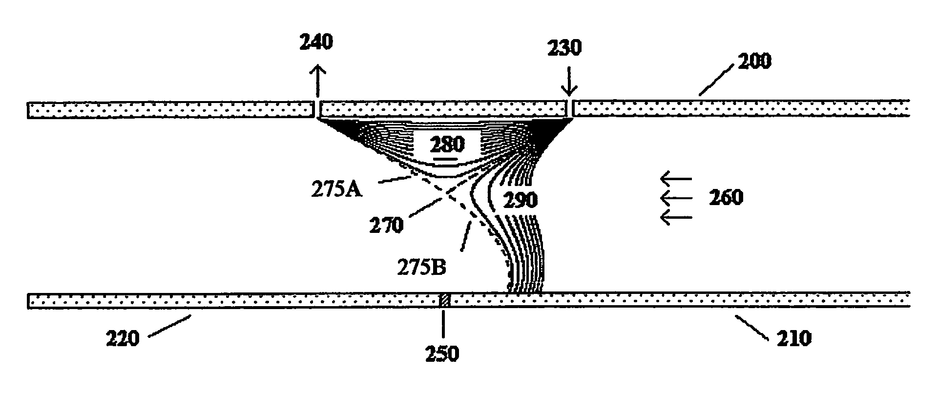
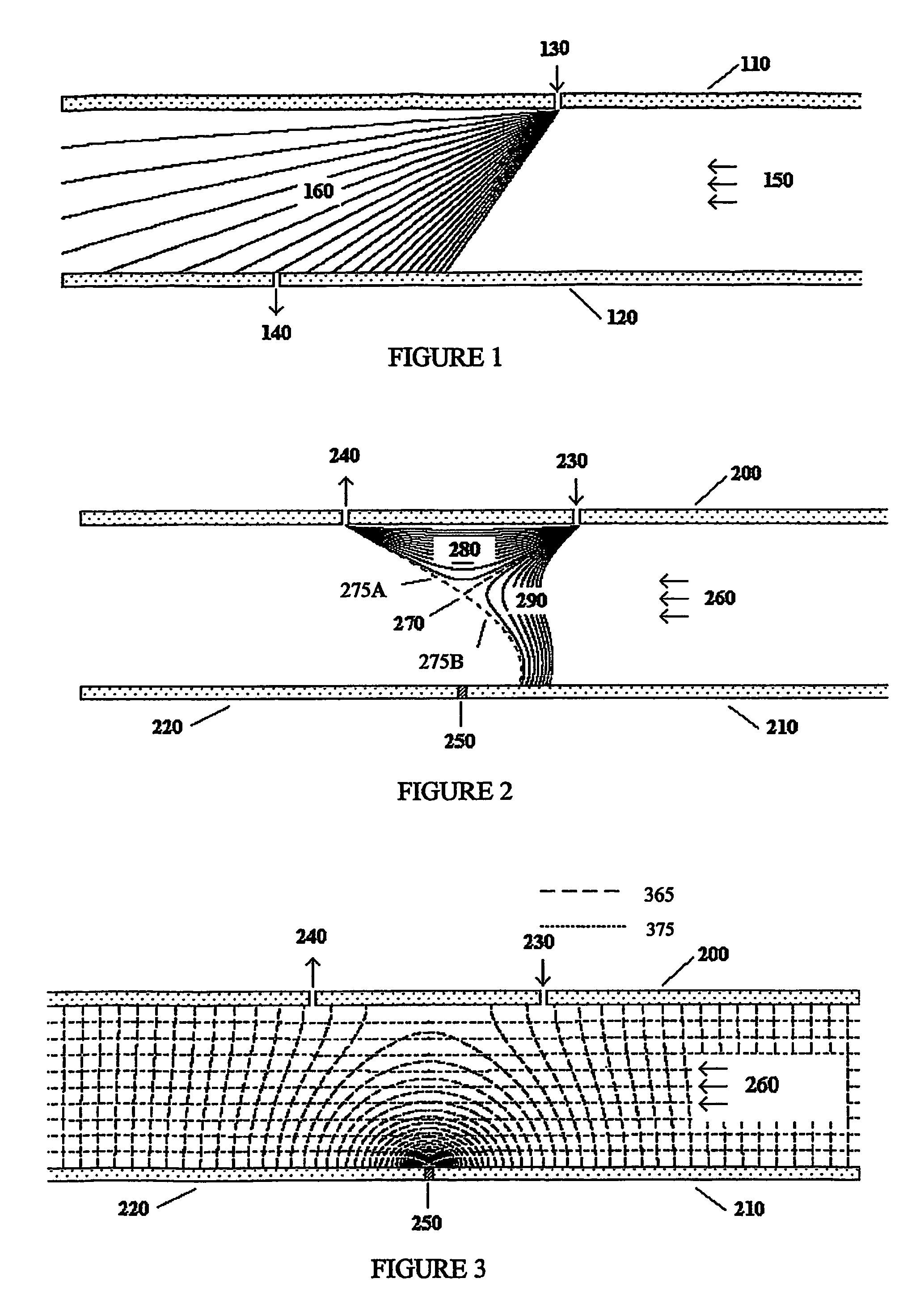
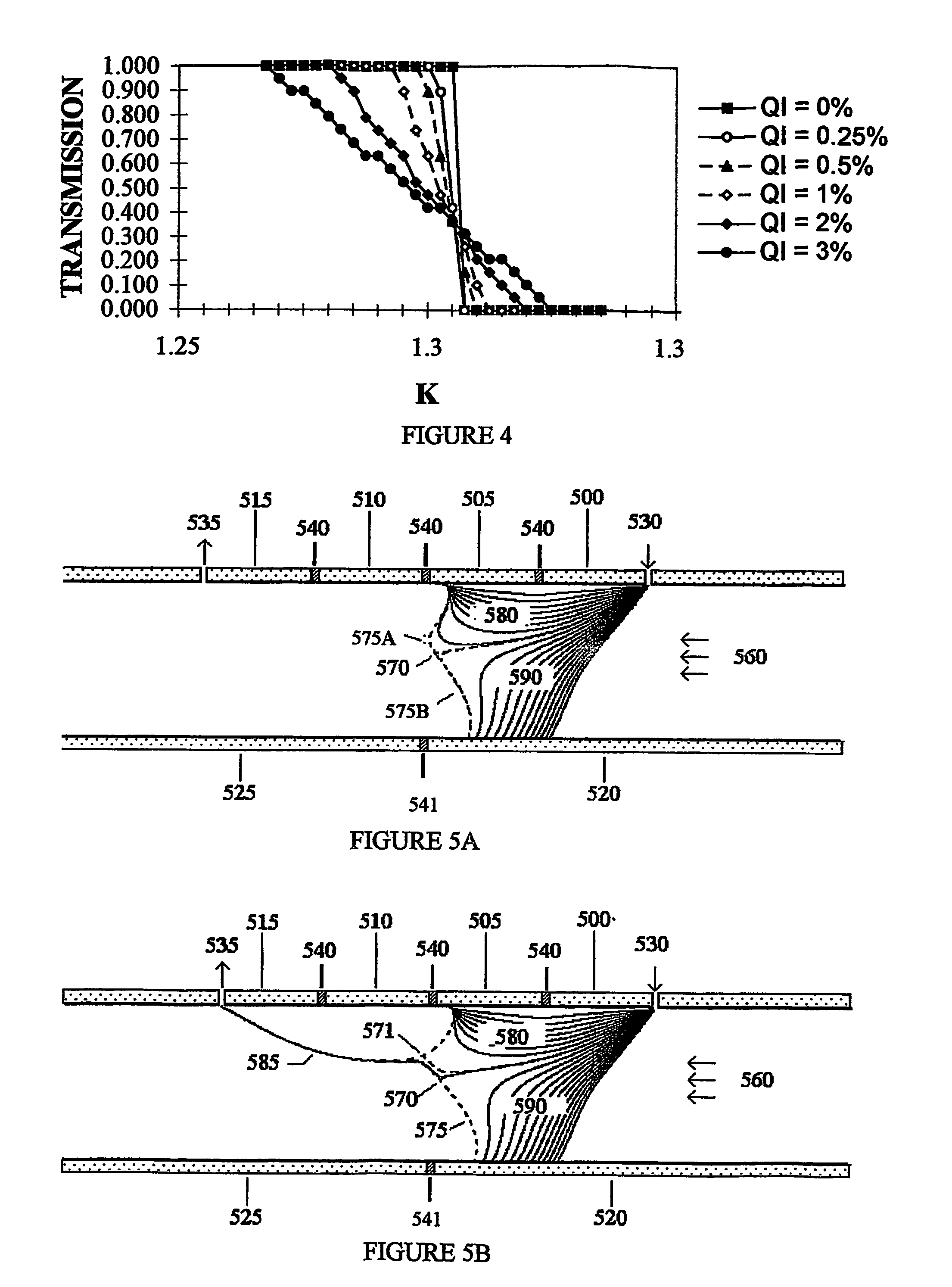
[0041]The present invention has many possible embodiments. The purpose of the following sections is to show a few of these embodiments which demonstrate how specially configured elements can be used to obtained the desired characteristics. Others embodiments should be obvious to those skilled in the art. FIG. 2 shows one embodiment of the current invention. The device shown is similar to the one shown in FIG. 1. It has a top plate (200) and a parallel bottom plate. In contrast to FIG. 1, the bottom “plate” has two elements (210,220). There is a voltage difference between the bottom left (220) and bottom right elements (210). A “junction” (250) separates the bottom left (220) and bottom right (210) elements and enables these elements to be at different voltages. To be considered a junction, the junction must be sufficiently near the analyzing region so the strong electrical fields near the junction affect the trajectories of the ions in the analyzing region. Phys...


PUM

PropertyMeasurementUnit
Reynolds numberaaaaaaaaaa
anglesaaaaaaaaaa
angleaaaaaaaaaa

Abstract

The invention describes a system and method to separate ions (and charged particles) suspended in gas based on their ion electrical mobility. Most common ion mobility analyzers involve two parallel plate (or concentric cylinder) elements (electrodes) between which is imposed an electrical field perpendicular to a sheath gas flow field between the cylinders. Separation occurs because high mobility ions tend to follow the electrical field while low mobility ions tend to follow the flow field. This invention describes various configurations of electrical elements and sheath gas flow fields for ion mobility separation devices with unique performance characteristics. These characteristics include devices in which: the ion inlet and outlet are on the same element; the inlet and outlet are at the same voltage; the outlet is upstream from the inlet; the outlet is on the axis; the inlet is on the axis; and the ions are focused on the outlet.

Description

CROSS-REFERENCE TO RELATED APPLICATIONS[0001]This application claims the benefit of U.S. Provisional Patent Application No. 60 / 449,080 filed Feb. 22, 2003 which is incorporated by reference herein in its entirety.STATEMENT REGARDING FEDERALLY SPONSORED RESEARCH OR DEVELOPMENT[0002]Not relevant.REFERENCES TO SEQUENCE LISTING, TABLES OR COMPUTER PROGRAM LISTING APPENDIX ON COMPACT DISK[0003]None.BACKGROUND OF THE INVENTION[0004]1. Field of the Invention[0005]This invention generally relates to a method and apparatus for sizing and classifying ions suspended in gas based on their ion mobility.[0006]2. Description of the Related Art[0007]The separation and / or sizing of ions according to their different mobilities is widely used for a variety of applications. There term “ion” is used here to include not only molecular ions but also charged particles. Devices that separate ions by their ion mobilities (Z) will be referred to here as “Mobility Analyzers” (MA), even though their use may be ...

Claims


Application Information

Patent Timeline
Patent Type & Authority Patents(United States)
IPC IPC(8): B01D59/44H01J49/00G01NG01N27/64H01J49/04H01J49/40
CPCG01N27/622G01N15/0266
Inventor LABOWSKY, MICHAEL J.FERNANDEZ DE LA MORA, JUAN
Owner LABOWSKY MICHAEL J
Learn More