Piezo-injector driving apparatus

a piezoelectric element and injector technology, applied in the direction of electric control, generator/motor, machine/engine, etc., can solve the problems of large noise generated by the injector, increase in energy loss, and inability to precisely control the final shift amount of the piezoelectric element, etc., to achieve high responsiveness

Active Publication Date: 2009-12-01
DENSO CORP
View PDF15 Cites 48 Cited by
  • Summary
  • Abstract
  • Description
  • Claims
  • Application Information

AI Technical Summary

Benefits of technology

[0009]The present invention therefore has an object to provide a piezo-injector driving apparatus that can suitably overcome disadvantages occurring at the start and the end of charging or discharging of a piezoelectric element while maintaining high responsiveness.
[0010]According to a first aspect, a driving apparatus for a piezo-injector including a piezoelectric element has a driving circuit for controlling electrical state amounts of the piezoelectric element that have a correlation with amounts of expansion and contraction of the piezoelectric element. The apparatus also has a setting circuit and an operation circuit. The setting circuit, in control of at least one of the expansion and contraction of the piezoelectric element, sets the electrical state amounts to increase an absolute value of a change rate of the electrical state amounts after a start of the control, and decrease the absolute value of a change rate of the electrical state amounts before and end of the control. The operation circuit operates the state amounts via the driving circuit to match the set state amounts.
[0011]According to a second aspect, the setting circuit sets the state amounts to decrease a change rate of electrical energy of the piezoelectric element at an end of charging the piezoelectric element. The operation circuit operates the state amounts via the driving circuit to match the set state amounts.
[0012]According to a third aspect, the setting circuit that sets the state amounts to increase the absolute value of a change rate of the electrical state amounts of the piezoelectric element after the start of discharging the piezoelectric element. The operation circuit operates the state amounts via the driving circuit to match the set state amounts.

Problems solved by technology

The following problems may occur with the chopper control in such a mode.
Since an energy change is large at the start of charging or discharging the piezoelectric element, a large noise is generated when the injector is driven.
Since an increase in the vibration causes an increase in energy loss, a final shift amount of the piezoelectric element cannot be precisely controlled.
In this case, however, it takes longer to open or close the valve of the piezo-injector.
Since one merit of the piezo-injector is to have higher responsiveness than injectors employing an electromagnetic solenoid or the like as an actuator, reducing the absolute value of a change rate of electrical energy may cause loss of the merit.
Without being limited to the case where electrical state amounts of the piezoelectric element are operated in the above mode, in control of the expansion and contraction of the piezoelectric element, the above problem generally occurs due to an increase of a change in electrical state amounts at the start or the end of charging or discharging.

Method used


Image

  • Piezo-injector driving apparatus
  • Piezo-injector driving apparatus
  • Piezo-injector driving apparatus

Examples


first embodiment

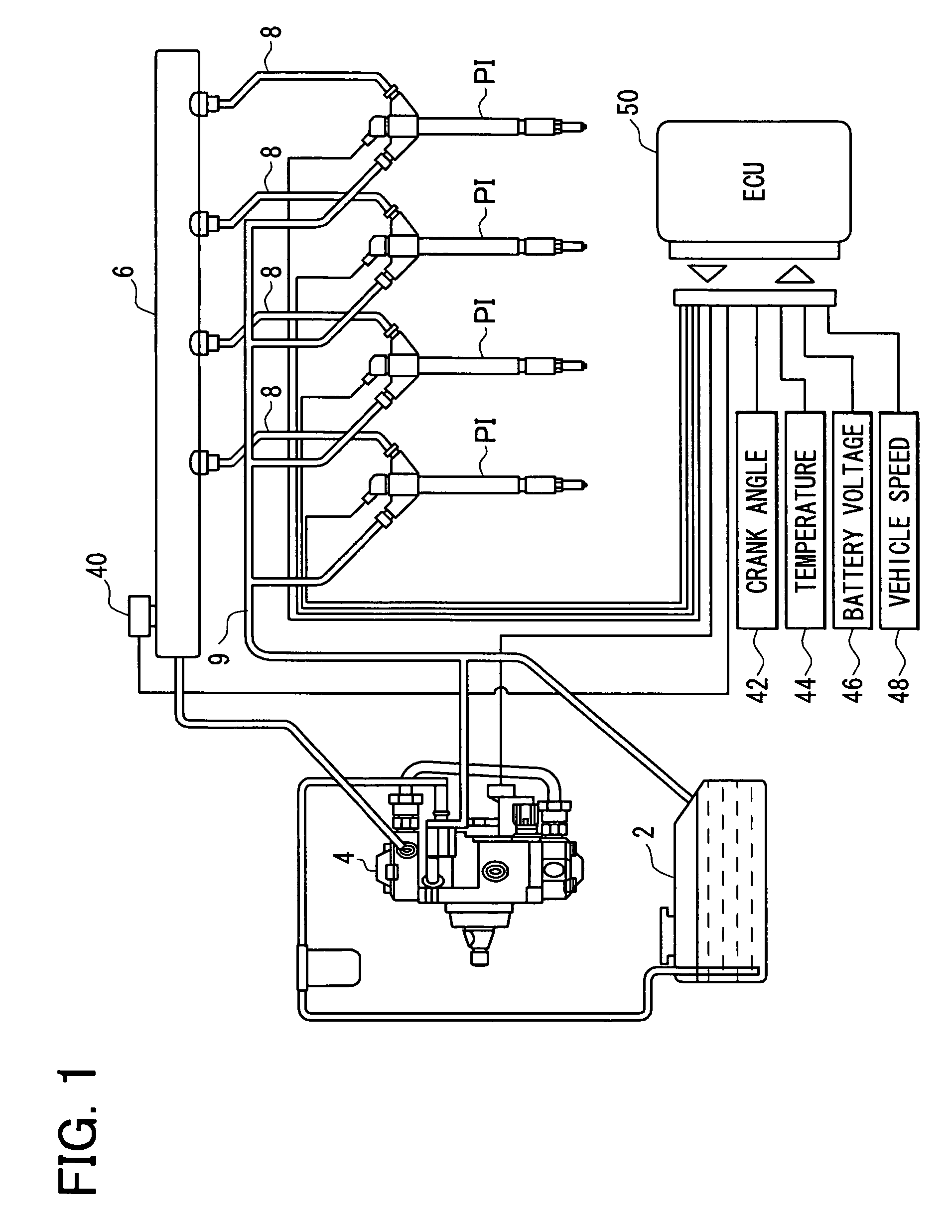
[0030]In a diesel engine system shown in FIG. 1, fuel in a fuel tank 2 is pumped up by a high-pressure fuel feed pump 4, and fed under pressure to a common rail 6. The fuel stored under high pressure in the common rail 6 is fed to a piezo-injector PI provided at each of cylinders of a four-cylinder diesel engine via a high-pressure fuel passage 8. Each piezo-injector PI is connected to a low-pressure fuel passage 9 to return fuel leaking from it to the fuel tank 2.

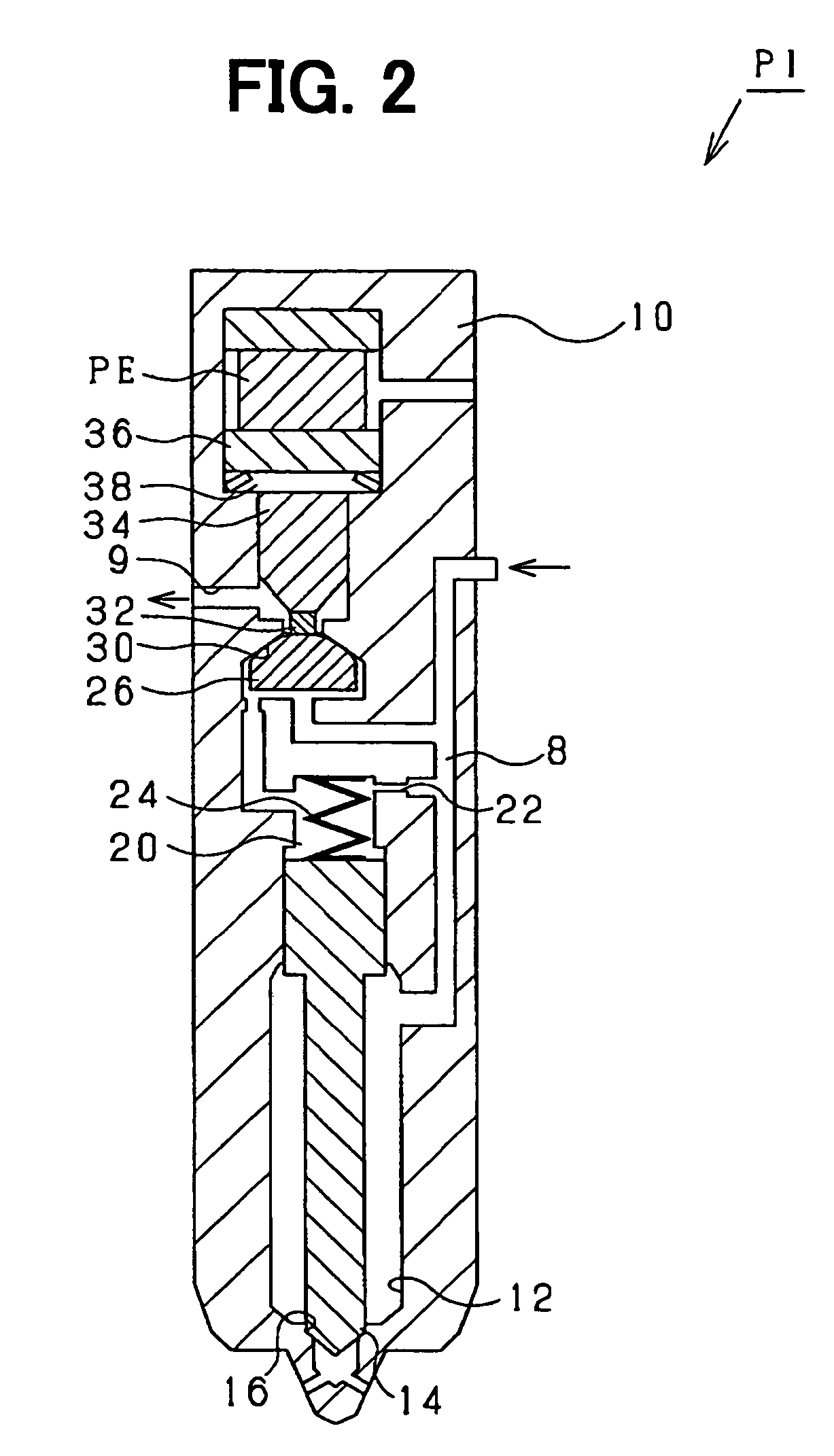
[0031]The piezo-injector P1 may be constructed as shown in FIG. 2. Specifically, a columnar needle storing part 12 is provided in a body 10 of piezo-injector PI. The needle storing part 12 stores a nozzle needle 14 movable in its axial direction. When the nozzle needle 14 is seated in a ring-like needle seat part 16 formed in the top end of body 10, the needle storing part 12 is separated from the outside (combustion chamber of the diesel engine). On the other hand, when the nozzle needle 14 leaves the needle seat part 16,...

second embodiment

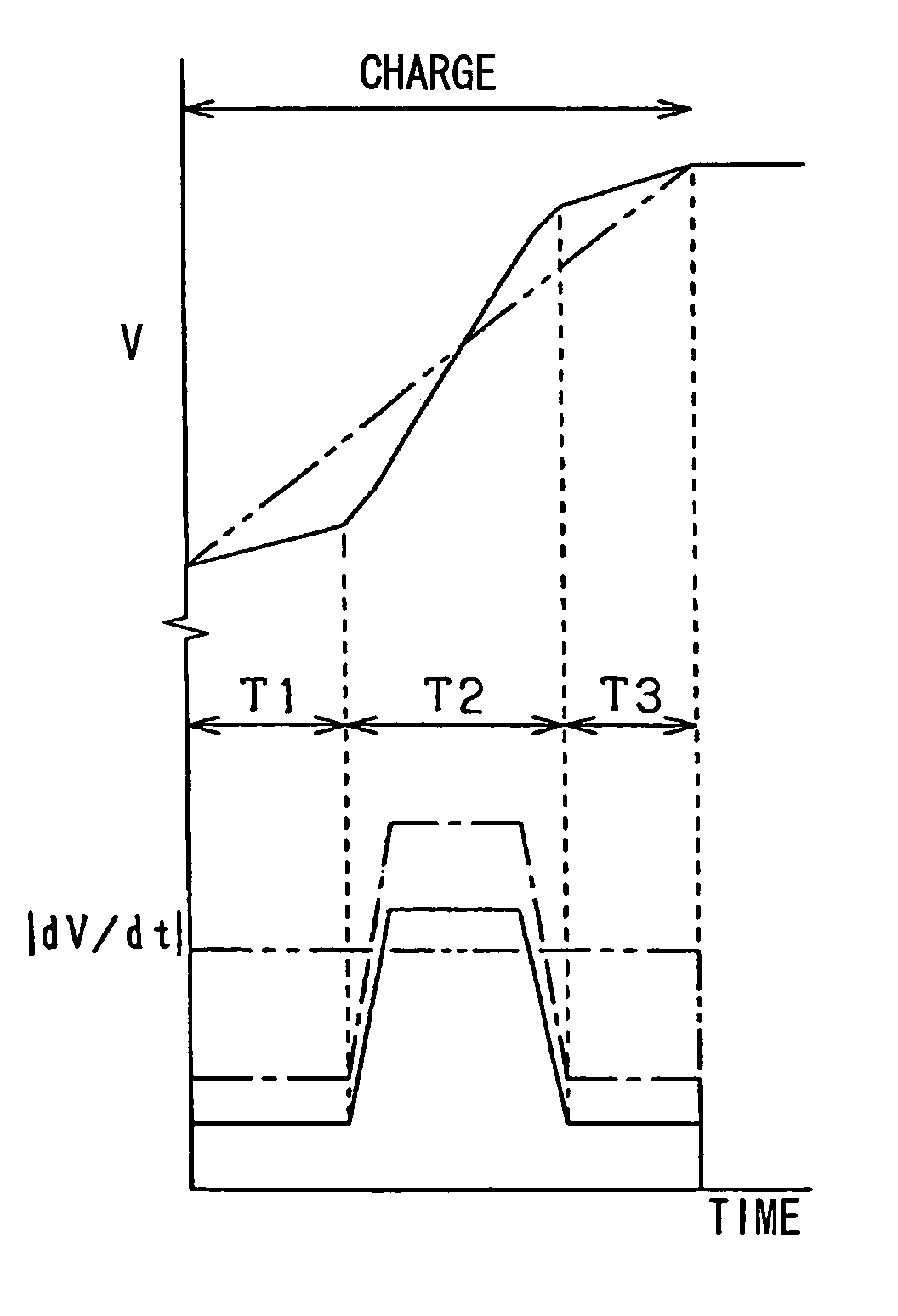
[0080]The capacitance of the piezoelectric element PE tends to change greatly depending on temperatures. Accordingly, even if the same operation voltage is applied, the amount of expansion or contraction (shift amount) of the piezoelectric element PE may change depending on temperatures. When voltages applied to the piezoelectric element PE are operated to control the expansion and contraction of the piezoelectric element PE, the expansion rate and the contraction rate of the piezoelectric element PE also change depending on temperatures. Accordingly, control of the expansion and contraction of the piezoelectric element PE that uses voltages applied to the piezoelectric element PE as operation amounts involves difficulties attributed to a change in temperatures of the piezoelectric element PE.

[0081]In the second embodiment, as an operation amount for controlling the expansion and contraction of the piezoelectric element PE, electrical energy flowing into the piezoelectric element PE...


PUM


Abstract

A piezo-injector driving apparatus overcomes disadvantages occurring at the start and the end of charging or discharging of a piezoelectric element while maintaining high responsiveness. At the start and the end of charging a piezoelectric element, the absolute value of a change rate of electrical energy of the piezoelectric element is set lower than in a period between them. Therefore, the pattern of electrical energy of the piezoelectric element is in the shape of the letter S. This prevents an excess of energy supplied to the piezoelectric element at the start of charging and energy supplied to the piezoelectric element at the end of charging.

Description

CROSS REFERENCE TO RELATED APPLICATION[0001]This application is based on and incorporates herein by reference Japanese Patent Application No. 2005-170319 filed on Jun. 10, 2005.FIELD OF THE INVENTION[0002]The present invention relates to an apparatus for driving a piezo-injector including a piezoelectric element as an actuator.[0003]A conventional piezo-injector driving apparatus controls the expansion and contraction of a piezoelectric element by charging or discharging the piezoelectric element in a multi-switching manner. The multi-switching manner charges and discharges the piezoelectric element while repeatedly increasing and decreasing the amount of current flowing via the piezoelectric element by repeatedly turning on and off a switching device by chopper control.[0004]The capacitance of the piezoelectric element changes greatly with temperatures. Accordingly, even if an electrical state amount having a correlation with an expansion and contraction amount of the piezoelectric...

Claims


Application Information

Patent Timeline
Patent Type & Authority Patents(United States)
IPC IPC(8): H01L41/09
CPCF02D41/2096H02N2/067F02D2041/2003F02D2200/0604F02D2200/501F02D2200/0602
Inventor NAGASE, NOBORU
Owner DENSO CORP
Why Eureka
Try Eureka