Enhanced video metrology tool

a video metrology and tool technology, applied in the field of machine vision inspection systems, can solve the problems of limited features and graphical user interface controls for video tools, particularly dimensional metrology video tools, and the resulting video tool parameters are set, so as to achieve a high level of control over the creation of tool parameters and the precise way to create tools

Active Publication Date: 2009-12-01
MITUTOYO CORP
View PDF15 Cites 99 Cited by
  • Summary
  • Abstract
  • Description
  • Claims
  • Application Information

AI Technical Summary

Benefits of technology

[0010]Currently, the users of precision machine vision inspection systems may spend a majority of their part-programming time setting up video tools and adjusting their parameters. Thus, even small improvements in their ease-of-use in comparison to their parameter customization capability, their GUI features, and other ergonomic factors, may be highly valued. The present invention is directed to novel and efficient instances of the video tools outlined above, as well as other video tools. A system and method for tool enhancements are provided which allow users to utilize video tools in a controlled manner. The video tools balance a minimal amount of cursor positioning and “mouse clicks” against a level of video tool “customization” control desired by a user when applying the video tools. Tool construction methods using multiple mouse clicks are provided as an alternative to using known drag-and-draw and one-click tool methods. The multi-click-plus and / or multi-click tools disclosed herein may convey more specific tool parameter information than known similar tools and provide a precise way to create tools. The multi-click-plus and / or multi-click tools disclosed herein may allow a user to determine a plurality of tool parameters with a single user action. These new video tool methods give users a high level of control over tool parameter creation with a simple and / or minimum set of user actions.

Problems solved by technology

The currently available features and graphical user interface (GUI) controls for video tools, and particularly dimensional metrology video tools, are limited.
Some existing video tools require relatively few “setup” actions by the user, but have the disadvantage that many of the resulting video tool parameters are set to default values that may be inappropriate in many situations.
Other existing video tools allow the video tool parameters to be extensively adjusted or customized by the user, but have the disadvantage that they require several independent setup actions by the user.

Method used


Image

  • Enhanced video metrology tool
  • Enhanced video metrology tool
  • Enhanced video metrology tool

Examples


Embodiment Construction

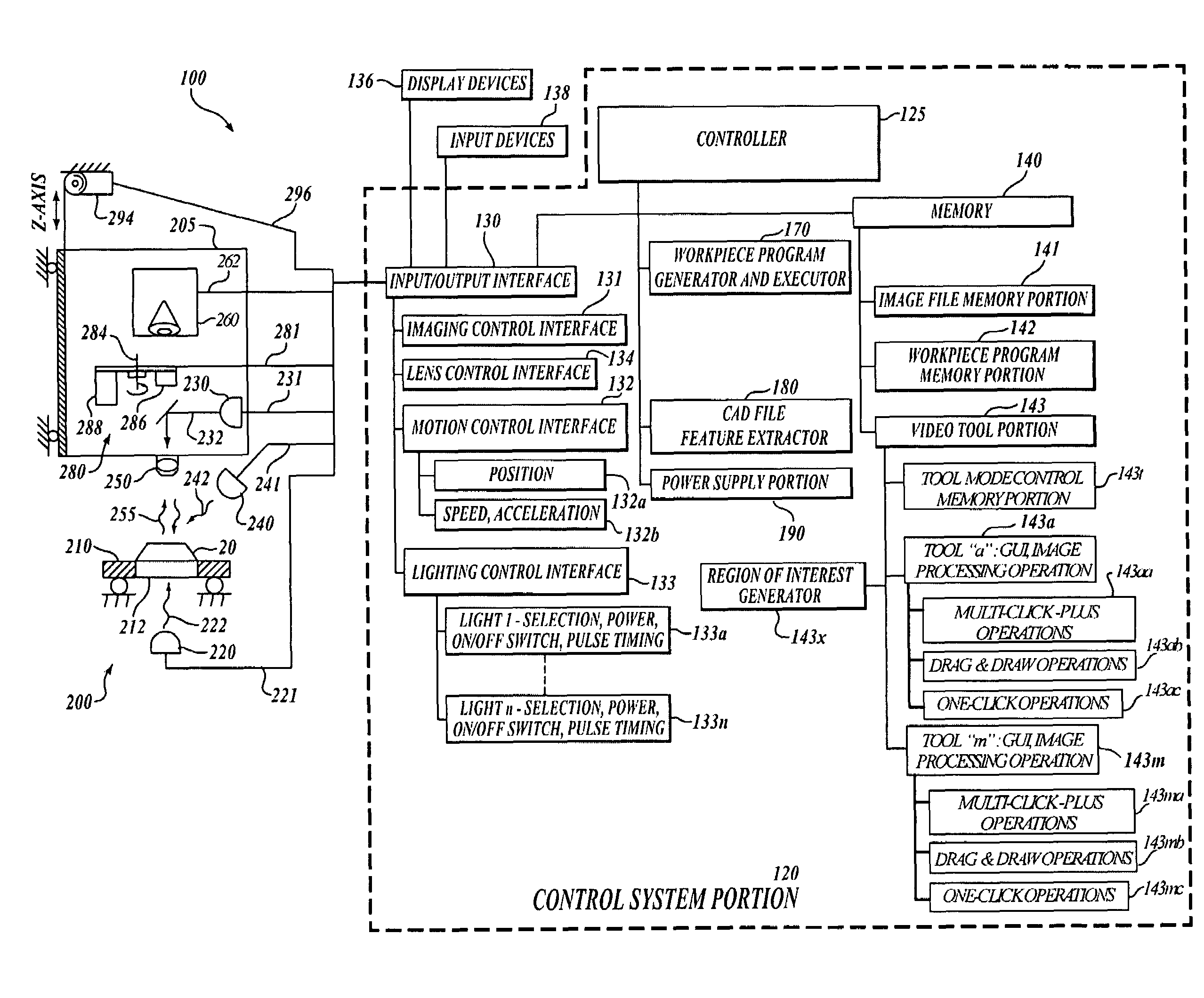
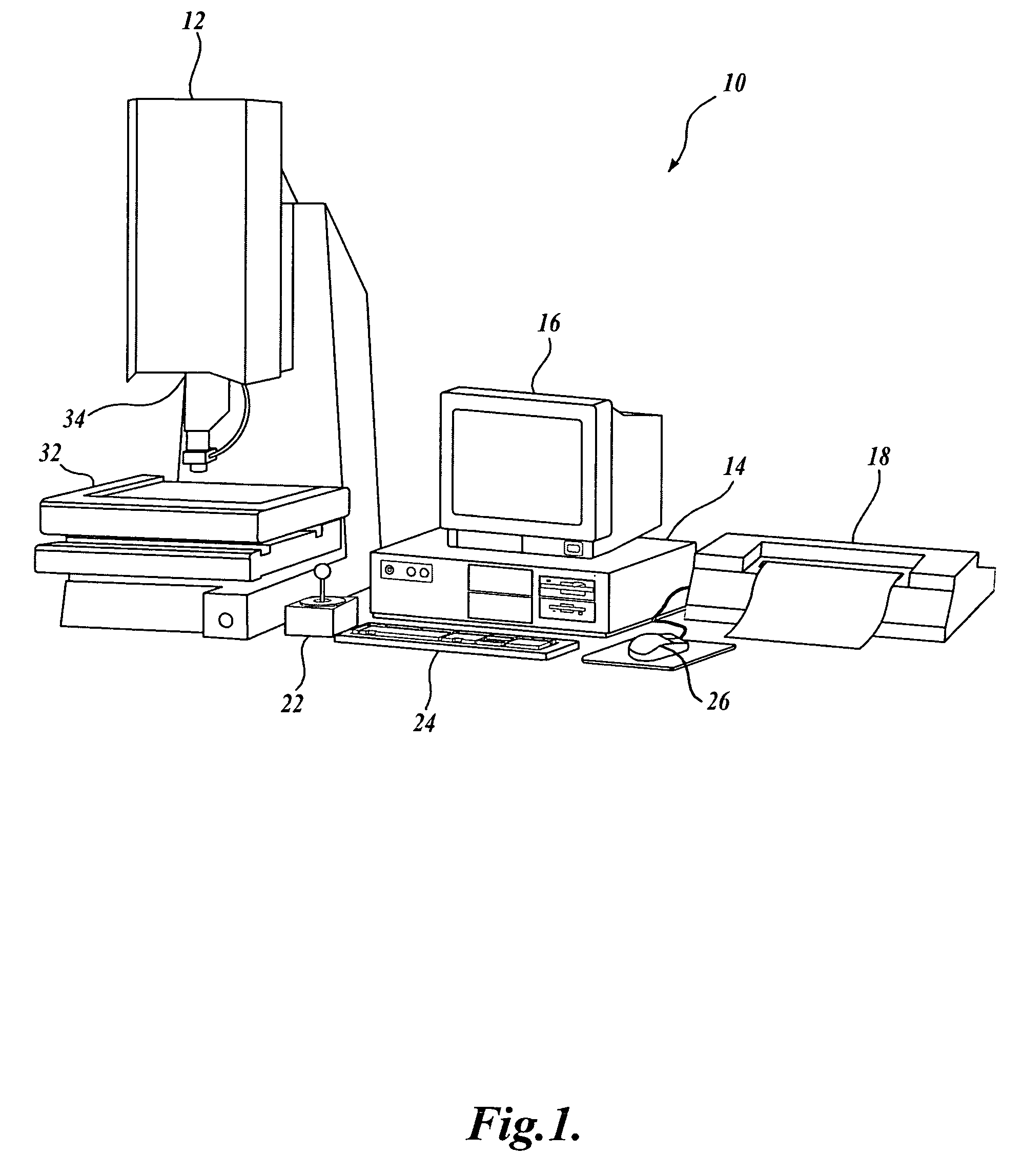
[0024]FIG. 1 is a block diagram of one exemplary machine vision inspection system 10 usable in accordance with the present invention. The machine vision inspection system 10 includes a vision measuring machine 12 that is operably connected to exchange data and control signals with a controlling computer system 14. The controlling computer system 14 is further operably connected to exchange data and control signals with a monitor or display 16, a printer 18, a joystick 22, a keyboard 24, and a mouse 26. The monitor or display 16 may display a user interface suitable for controlling and / or programming the operations of the machine vision inspection system 10.

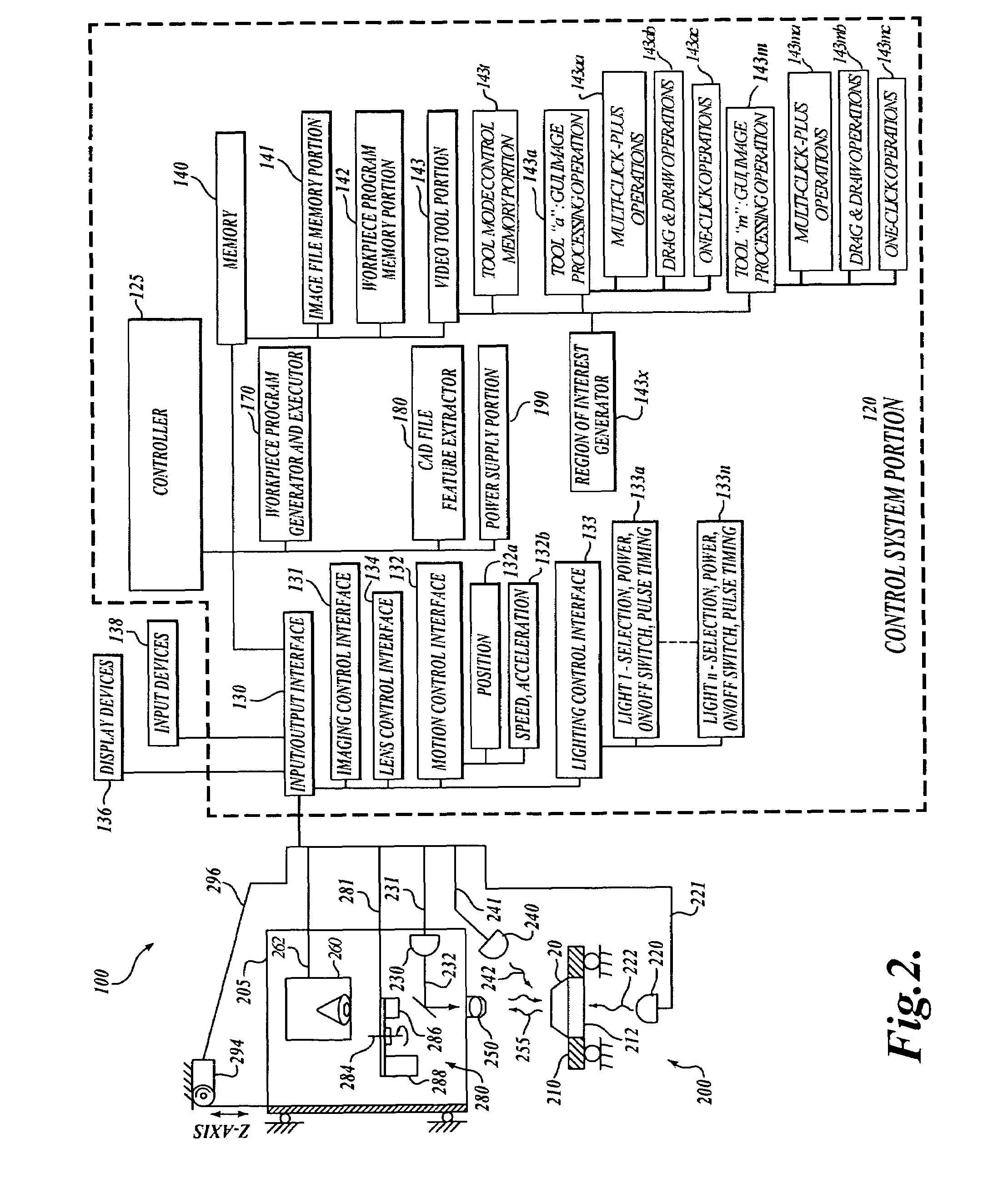
[0025]The vision measuring machine 12 includes a moveable workpiece stage 32 and an optical imaging system 34 which may include a zoom lens or interchangeable lenses. The zoom lens or interchangeable lenses generally provide various magnifications for the images provided by the optical imaging system 34. The machine vision inspect...


PUM


Abstract

A system and method for tool enhancements are provided which allow users to utilize video tools in a controlled manner. The video tools balance a minimal amount of cursor positioning and “mouse clicks” against a level of video tool “customization” control desired by a user when applying the video tools. Tool construction methods using multiple mouse clicks are provided as an alternative to using drag-and-draw and one-click tools. Multi-click-plus tools give more specific information and provide a precise way to rapidly create customized tools.

Description

CROSS-REFERENCE TO RELATED APPLICATION[0001]This application claims the benefit of U.S. Provisional Application No. 60 / 648,956, filed Jan. 31, 2005, under the provisions of 35 U.S.C. § 119.FIELD OF THE INVENTION[0002]The invention relates generally to machine vision inspection systems, and more particularly to video metrology tools usable to define inspection operations for such systems.BACKGROUND OF THE INVENTION[0003]Precision machine vision inspection systems (or “vision systems” for short) can be utilized to obtain precise dimensional measurements of inspected objects and to inspect various other object characteristics. Such systems may include a computer, a camera and optical system, and a precision stage that is movable in multiple directions so as to allow the camera to scan the features of a workpiece that is being inspected. One exemplary prior art system that is commercially available is the QUICK VISION® series of PC-based vision systems and QVPAK® software available from...

Claims


Application Information

Patent Timeline
Patent Type & Authority Patents(United States)
IPC IPC(8): G06K9/00
CPCG06T7/0004G01N21/8806
Inventor BLANFORD, CHARLESYU, DAHAISAYLOR, BARRY E.
Owner MITUTOYO CORP
Why Eureka
Try Eureka