On-channel repeater

a repeater and channel technology, applied in the field of broadcast transceivers, can solve the problems of direct interference of intermodulation products from adjacent channels, inability of domestic receivers to successfully demodulate wanted channels, instability and relaxation oscillation, etc., to avoid instability caused by parasitic coupling

Active Publication Date: 2009-12-01
BRITISH BROADCASTING CORP
View PDF54 Cites 26 Cited by
  • Summary
  • Abstract
  • Description
  • Claims
  • Application Information

AI Technical Summary

Problems solved by technology

In an on-channel repeater, due to unwanted coupling or feedback between the receiving and the transmitting antenna, the repeater can also receive its own retransmitted output, thus causing instability and relaxation oscillations.
In hole-filling, the received signal strength is sufficient, but signals on adjacent channels to the desired signal are so strong that domestic receivers have insufficient dynamic range to demodulate the wanted channel successfully.
In extreme cases, in areas very close to adjacent channel transmitters, the intermodulation products from the adjacent channels interfere directly with the wanted signal, even though spectral mask requirements have been fulfilled.

Method used


Image

  • On-channel repeater
  • On-channel repeater
  • On-channel repeater

Examples


Embodiment Construction

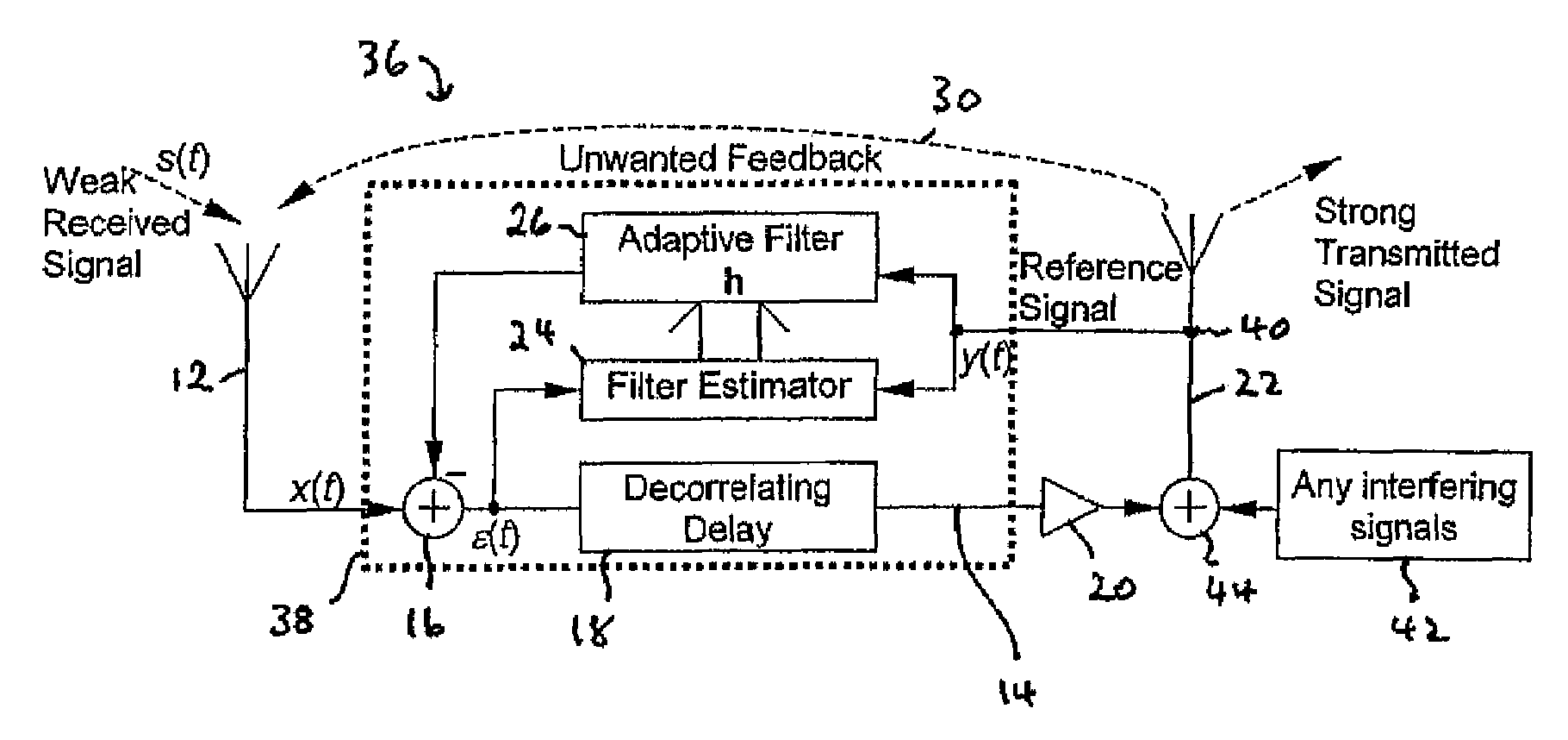
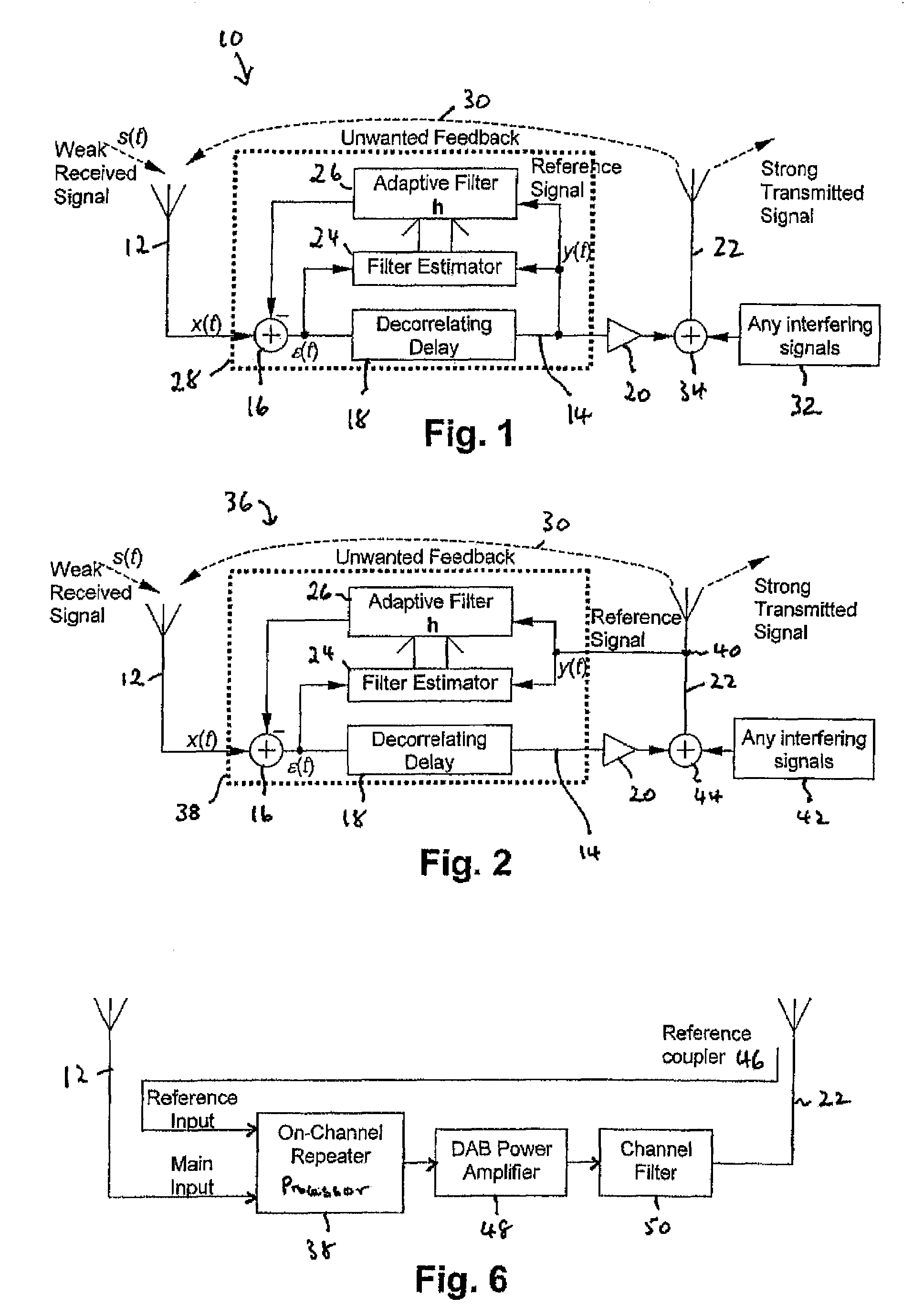
[0019]An on-channel repeater 36 embodying the invention will now be described in more detail. Referring to FIG. 2, much of the structure of the processor 38 is as described for the processor 28 of FIG. 1. That is to say the transceiver 36 has a receiving antenna 12 which is coupled to an amplification path 14 which includes an adder 16, a decorrelating delay 18, and an amplifier 20. The output of the amplifier is applied to a transmitting antenna 22. A reference signal is applied to a filter estimator 24, which also receives the output of adder 16, and an adaptive filter 26, which applies an output to the subtractive or inverting input of adder 16. The filter estimator 24 generates filter coefficients which are applied to the adaptive filter 26.

[0020]The differences from FIG. 1 are first that in this case the reference signal, that is the input to the adaptive filter 26 and the reference input to the filter estimator 24, are taken not from within the processor 38 but rather from the...


PUM


Abstract

An on-channel repeater has a receiving antenna for receiving an RF signal and a transmitting antenna for transmitting on the same frequency as the input signal. An amplification path between the antennas provides substantially linear processing and includes a combiner, a decorrelating delay and a power amplifier. A filter estimator receives a reference signal and the combiner output and generates a plurality of control coefficients which are applied to an adaptive filter which filters the reference signal accordingly and applies its output to the combiner. The reference signal is derived not from the output of the decorrelating delay but rather from the output antenna after the power amplifier. Where there is an adjacent transmitter generating potentially interfering signals, the transmitter output is coupled to the same transmitter antenna.

Description

CROSS REFERENCE TO RELATED APPLICATIONS[0001]This application claims the benefit under 35 U.S.C. §119 of United Kingdom application no. 0510385.8 filed May 20, 2005.STATEMENT REGARDING FEDERALLY SPONSORED RESEARCH[0002]Not applicable.BACKGROUND OF THE INVENTION[0003]This invention relates to rebroadcast transceivers which are designed to receive RF (radio frequency) signals, amplify them, and retransmit them onward on the same frequency. Such transceivers are known in the broadcasting field as on-channel repeaters, and are sometimes termed active deflectors.[0004]In an on-channel repeater, due to unwanted coupling or feedback between the receiving and the transmitting antenna, the repeater can also receive its own retransmitted output, thus causing instability and relaxation oscillations. Our International Patent Application WO97 / 16942 and European Patent Application 772310 (equivalent GB 2306082) describe a method and apparatus which has been found to be surprisingly effective in r...

Claims


Application Information

Patent Timeline
Patent Type & Authority Patents(United States)
IPC IPC(8): H04B7/14H03K11/00H04R27/00H04L25/64H04L25/60H04B15/00H04B7/17H04B7/185H04L25/52H04L25/20H04B17/02H04B3/36H04B7/155H04B17/40H04L25/24H04L27/26
CPCH04B1/525H04L25/24H04B7/15585H04L27/2601
Inventor MOSS, PETER NEIL
Owner BRITISH BROADCASTING CORP
Why Eureka
Try Eureka