
Atomic memory operators in a parallel processor

a technology of atomic memory and parallel processor, applied in the field of parallel processor, can solve problems such as reducing the performance benefit of parallel processing, corrupting value-dependent updates, and affecting the operation of the processor

Active Publication Date: 2009-12-01
NVIDIA CORP
View PDF3 Cites 170 Cited by
  • Summary
  • Abstract
  • Description
  • Claims
  • Application Information

AI Technical Summary

Benefits of technology

The present invention introduces methods, apparatuses, and systems for updating data in memory while executing multiple threads of instructions. This is achieved by receiving a single instruction from one of a plurality of concurrently executing threads, reading data from a specific memory location, performing an operation involving the data, and storing the result to the specific memory location, without requiring separate load and store instructions. The single instruction can be forwarded to an execution unit capable of maintaining exclusive control of the memory location. The invention allows for atomic updates to memory, enabling parallel threads to perform parallel reductions on shared data efficiently, enabling parallel execution of dot products, histograms, voting, and similar algorithms where many concurrent threads contribute incremental values to shared results. The invention also enables parallel threads to manage shared data structures like semaphores, queues, lists, and trees.

Problems solved by technology

However in a parallel execution environment such updates to a region of memory can be problematic.
During these steps, another thread could perform a store to the same memory location, e.g. as part of its own multi-step update, thereby corrupting a value-dependent update.
Such traditional approaches involving separate instructions dedicated to the locking, loading, updating, storing, and unlocking of memory locations require significant time to execute, and serialize the parallel execution to one thread at each lock / unlock point, reducing the performance benefit of parallel processing.

Method used


Image

  • Atomic memory operators in a parallel processor
  • Atomic memory operators in a parallel processor
  • Atomic memory operators in a parallel processor

Examples


Embodiment Construction

Illustrative System Description

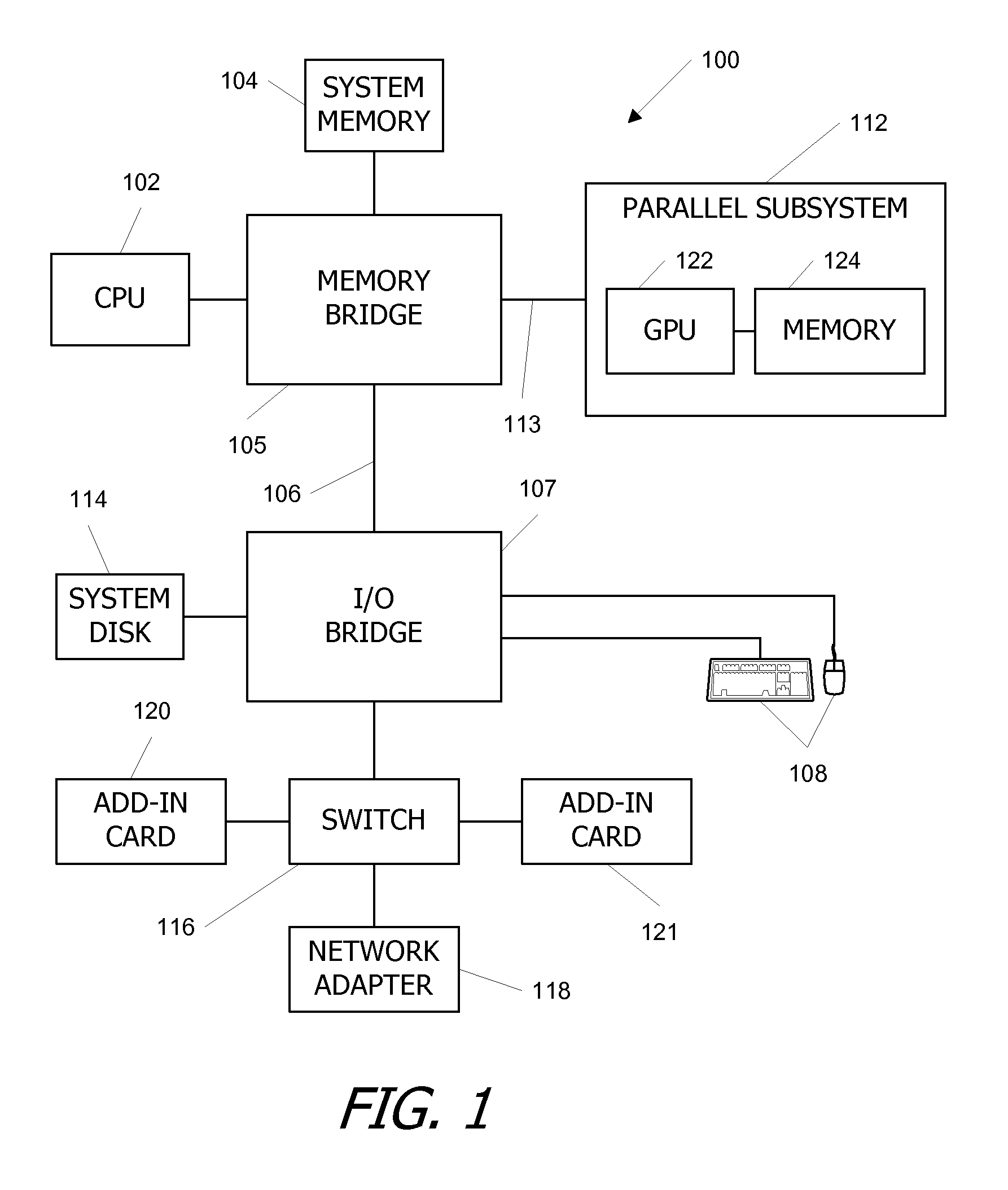
[0017]FIG. 1 is a block diagram of a computer system 100 according to an embodiment of the present invention.

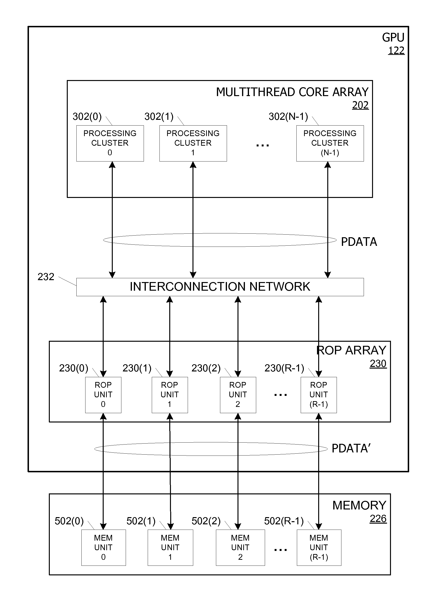
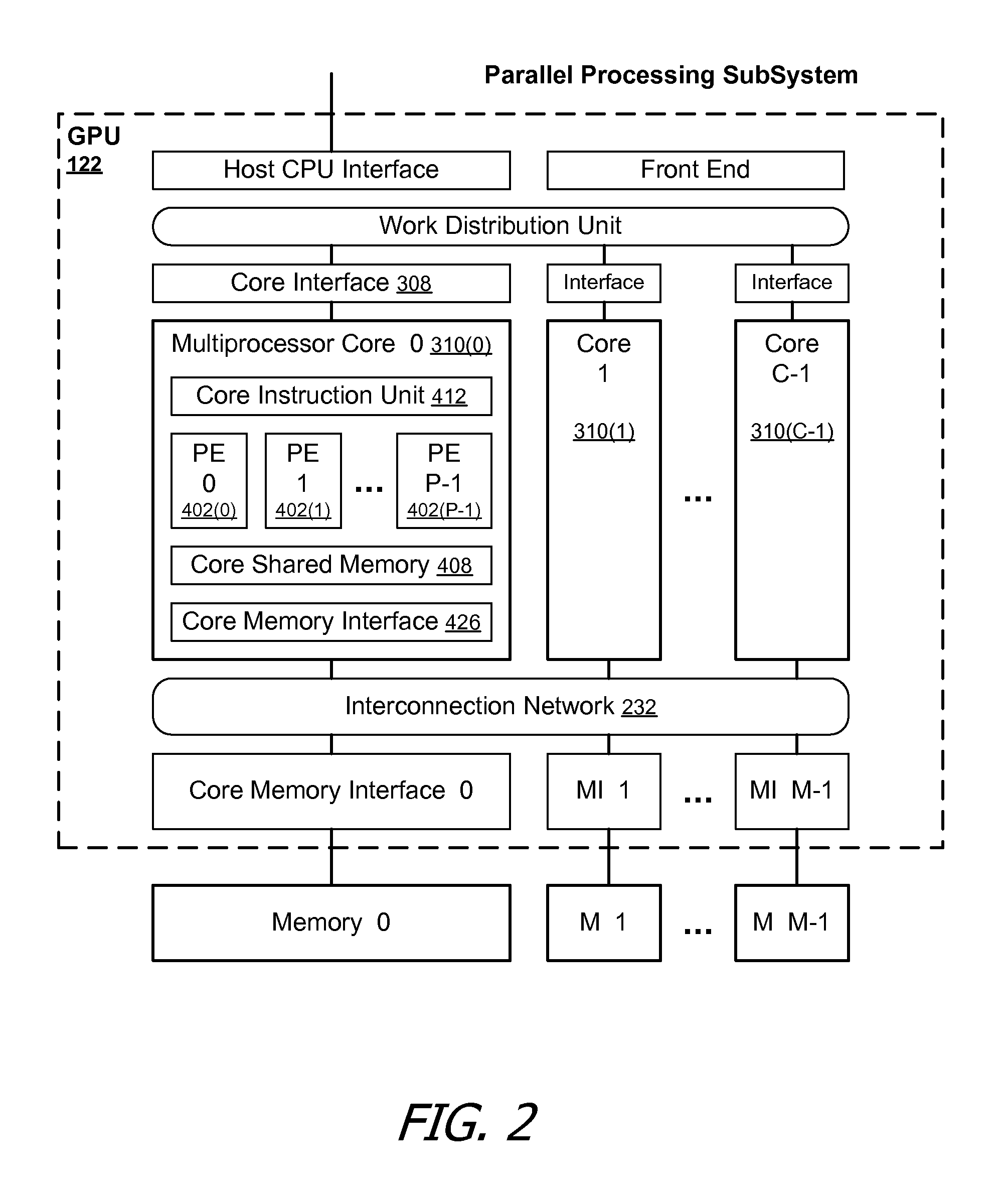
[0018]Parallel processing subsystem 112 includes a parallel processing unit or parallel graphics processing unit (GPU) 122 and a memory 124, which may be implemented, e.g., using one or more integrated circuit devices such as programmable processors, application specific integrated circuits (ASICs), field programmable gate arrays (FPGAs), and memory units.

[0019]CPU 102 operates as the control processor of system 100, controlling and coordinating operations of other system components. In particular, CPU 102 issues commands that control the operation of GPU 122. In some embodiments, CPU 102 writes a stream of commands for GPU 122 to a command buffer, which may be in system memory 104, memory 124, or another storage location accessible to both CPU 102 and GPU 122. GPU 122 reads the command stream from the command buffer and executes commands indepe...


PUM


Abstract

Methods, apparatuses, and systems are presented for updating data in memory while executing multiple threads of instructions, involving receiving a single instruction from one of a plurality of concurrently executing threads of instructions, in response to the single instruction received, reading data from a specific memory location, performing an operation involving the data read from the memory location to generate a result, and storing the result to the specific memory location, without requiring separate load and store instructions, and in response to the single instruction received, precluding another one of the plurality of threads of instructions from altering data at the specific memory location while reading of the data from the specific memory location, performing the operation involving the data, and storing the result to the specific memory location.

Description

BACKGROUND OF THE INVENTION[0001]In a parallel processor, many concurrently executing threads of instructions may be reading and writing to the same memory location independently, that is, without any coordination with one another. These reads and writes may be performed using traditional load and store instructions. However in a parallel execution environment such updates to a region of memory can be problematic. For example, a programmer may need to design the program of instructions in order to ensure, while one thread of instructions is updating the region of memory, the region of memory is not being modified by another thread. A typical update of a memory location involves a load, an update that depends on the load value, and a store to the memory location. During these steps, another thread could perform a store to the same memory location, e.g. as part of its own multi-step update, thereby corrupting a value-dependent update.[0002]The typical solution to this problem is to ca...

Claims


Application Information

Patent Timeline
Patent Type & Authority Patents(United States)
IPC IPC(8): G06F13/00G06F13/28
CPCG06F9/3001G06F9/30021G06F9/3004G06F9/30087G06F9/3824G06F9/3834G06F9/3851G06F9/526G06F13/4022G06T1/20G06F9/3887G06F9/30018G06F2209/521G09G5/363G09G5/393
Inventor BUCK, IAN A.NICKOLLS, JOHN R.SHEBANOW, MICHAEL C.NYLAND, LARS S.
Owner NVIDIA CORP
Learn More