Shuttering system for scanning projectors

a projector and scanning technology, applied in the field of scanning projection systems, can solve the problems of laser light damage to the eye, eye damage can occur, and the potential danger of laser ligh

Inactive Publication Date: 2009-12-08
EVANS & SUTHERLAND COMP
View PDF4 Cites 10 Cited by
  • Summary
  • Abstract
  • Description
  • Claims
  • Application Information

AI Technical Summary

Benefits of technology

[0009]It has been recognized that it would be advantageous to develop a laser shutter system for a scanning laser projector that prevents laser light from potentially contacting an individual's eye long enough to cause damage if the scanning device stops or drops below speed.
[0010]It has also been recognized that it would be advantageous to develop a laser shutter system that is significantly faster than mechanical shutter systems.
[0013]In accordance with another aspect thereof, the invention provides a method for rapidly preventing escape of laser light from a scanning laser projection system having a grating light valve light modulator and a scanning device. The method includes the steps of monitoring operation of the scanning device, and deactivating the light modulator upon detection of scanner malfunction.

Problems solved by technology

One challenge presented by laser scanning projection systems is the potential danger of laser light.
It is well known that eye damage can occur if laser light (above a certain level) remains on an individual's retina beyond a certain amount of time.
However, if the scanning device malfunctions and stops, allowing a single stationary concentrated beam of light to leave the projector, this could be very damaging if the beam contacts the individual's eye.
However, laser light can easily damage the eye in far less time.
Unfortunately, mechanical shutters, even micromechanical ones, lack the speed needed to block laser light fast enough to eliminate all possibility of hazard in case of slow down or stoppage of a scanning laser system.
However, prior systems known in the art do not provide a satisfactory method of stopping or controlling laser light from causing eye damage.

Method used


Image

  • Shuttering system for scanning projectors
  • Shuttering system for scanning projectors
  • Shuttering system for scanning projectors

Examples


Embodiment Construction

[0019]Reference will now be made to the exemplary embodiments illustrated in the drawings, and specific language will be used herein to describe the same. It will nevertheless be understood that no limitation of the scope of the invention is thereby intended. Alterations and further modifications of the inventive features illustrated herein, and additional applications of the principles of the inventions as illustrated herein, which would occur to one skilled in the relevant art and having possession of this disclosure, are to be considered within the scope of the invention.

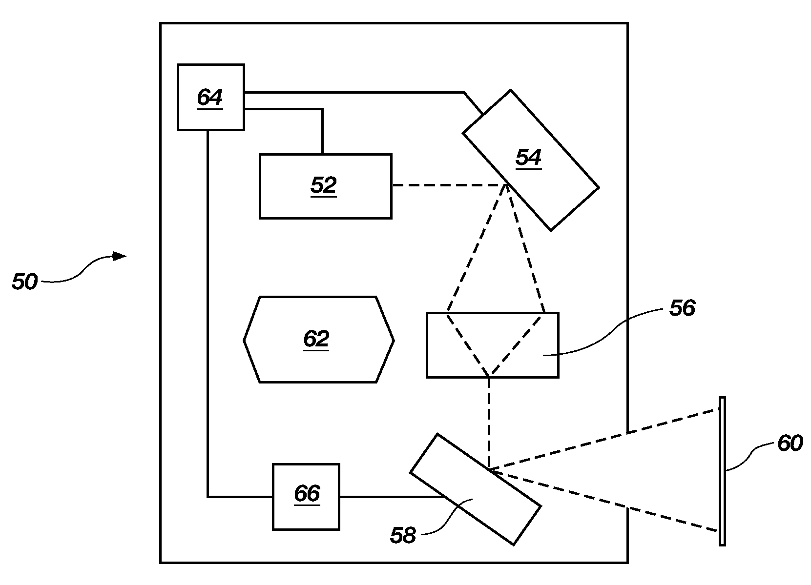
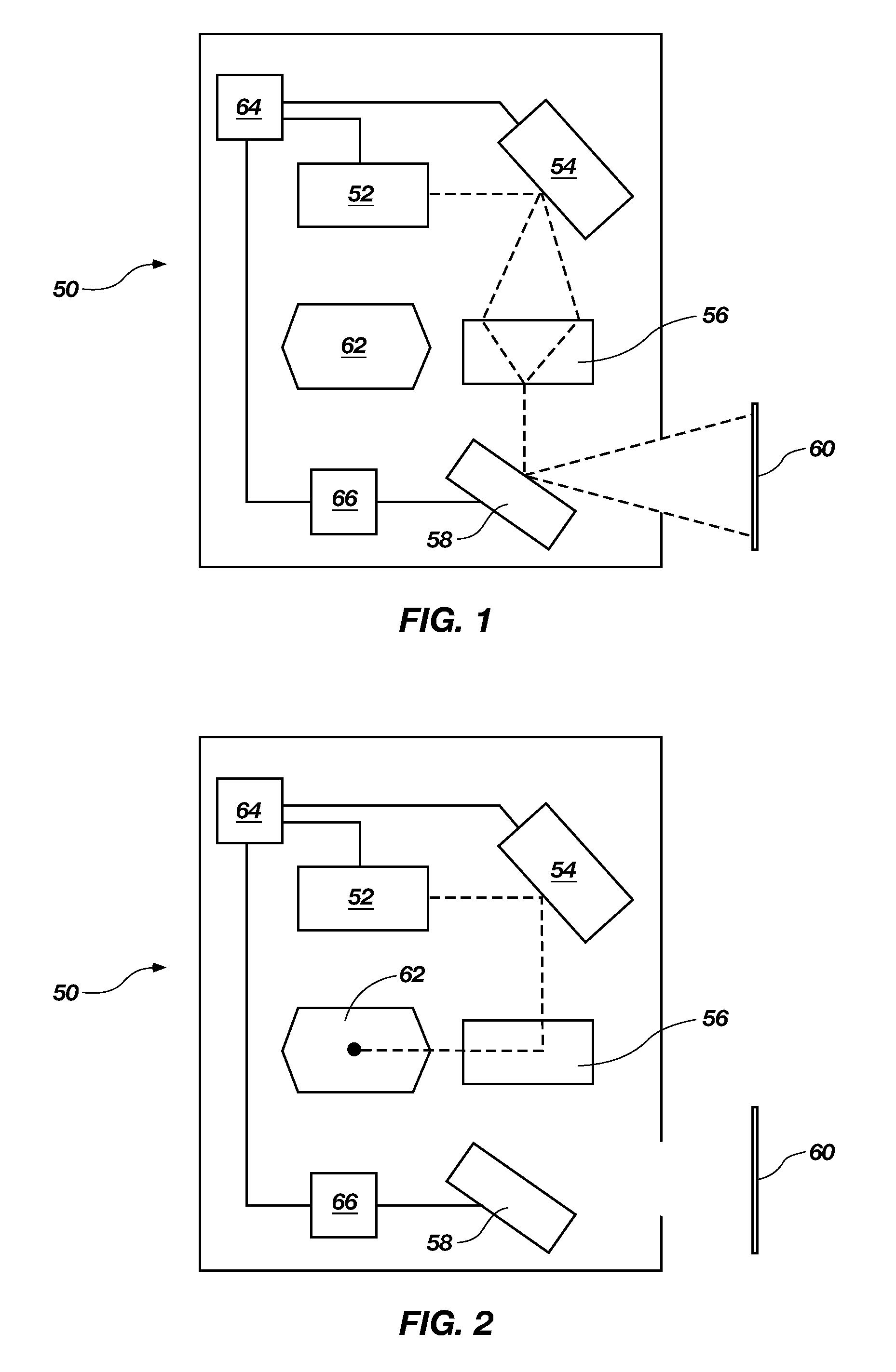
[0020]The invention provides a laser shuttering system that is configured to quickly and substantially reduce the amount of laser light exiting a laser projector. In response to possible system failure, the invention reduces the amount of time concentrated laser light could have in contact with the human eye, thus allowing a reduction in laser safety classification. Those skilled in the art will recognize that la...


PUM


Abstract

A shuttering system for a scanning projector having a laser source, a grating light valve light modulator, and a light steering scanner includes a feedback system interconnecting the scanner with the light modulator. The feedback system is configured to deactivate the light modulator in case of scanner malfunction, so as to redirect laser light away from the scanner.

Description

PRIORITY CLAIM[0001]This application claims priority from U.S. Provisional patent application Ser. No. 60 / 556,783, filed on Mar. 26, 2004.BACKGROUND OF THE INVENTION[0002]1. Field of the Invention[0003]The present invention relates generally to scanning projection systems. More particularly, the present invention relates to an electronic shuttering system for a scanning projector system.[0004]2. Related Art[0005]There are a variety of visual projection systems and methods that use lasers to scan an image onto a projection screen. One of these methods involves scanning a linear array to form an image using a grating light valve (GLV) to project a linear array on a screen. A GLV projection system can be used to produce an image on a flat screen, or can be used to produce a panoramic image on a curved screen.[0006]One challenge presented by laser scanning projection systems is the potential danger of laser light. It is well known that eye damage can occur if laser light (above a certai...

Claims


Application Information

Patent Timeline
Patent Type & Authority Patents(United States)
IPC IPC(8): G06K7/10G03B21/00G06K7/14
CPCG03B21/00G03B21/008G03B21/005G06K7/10G06K7/14
Inventor WINKLER, BRET D.WILLIAMS, FORREST L.
Owner EVANS & SUTHERLAND COMP
Why Eureka
Try Eureka