
Process and apparatus for forming uniform nanofiber substrates

a nanofiber and substrate technology, applied in the field of uniform nanofiber webs, can solve the problems of prohibitively high operating and equipment costs, limited market acceptance of commercial products, and inability to provide auxiliary air sources for web formation, so as to reduce the distance from which the fibers are located, improve the uniformity of the web, and reduce the interaction or comingling of the fibrous material

Active Publication Date: 2009-12-08
AVINTIV SPECIALTY MATERIALS INC
View PDF34 Cites 76 Cited by
  • Summary
  • Abstract
  • Description
  • Claims
  • Application Information

AI Technical Summary

Benefits of technology

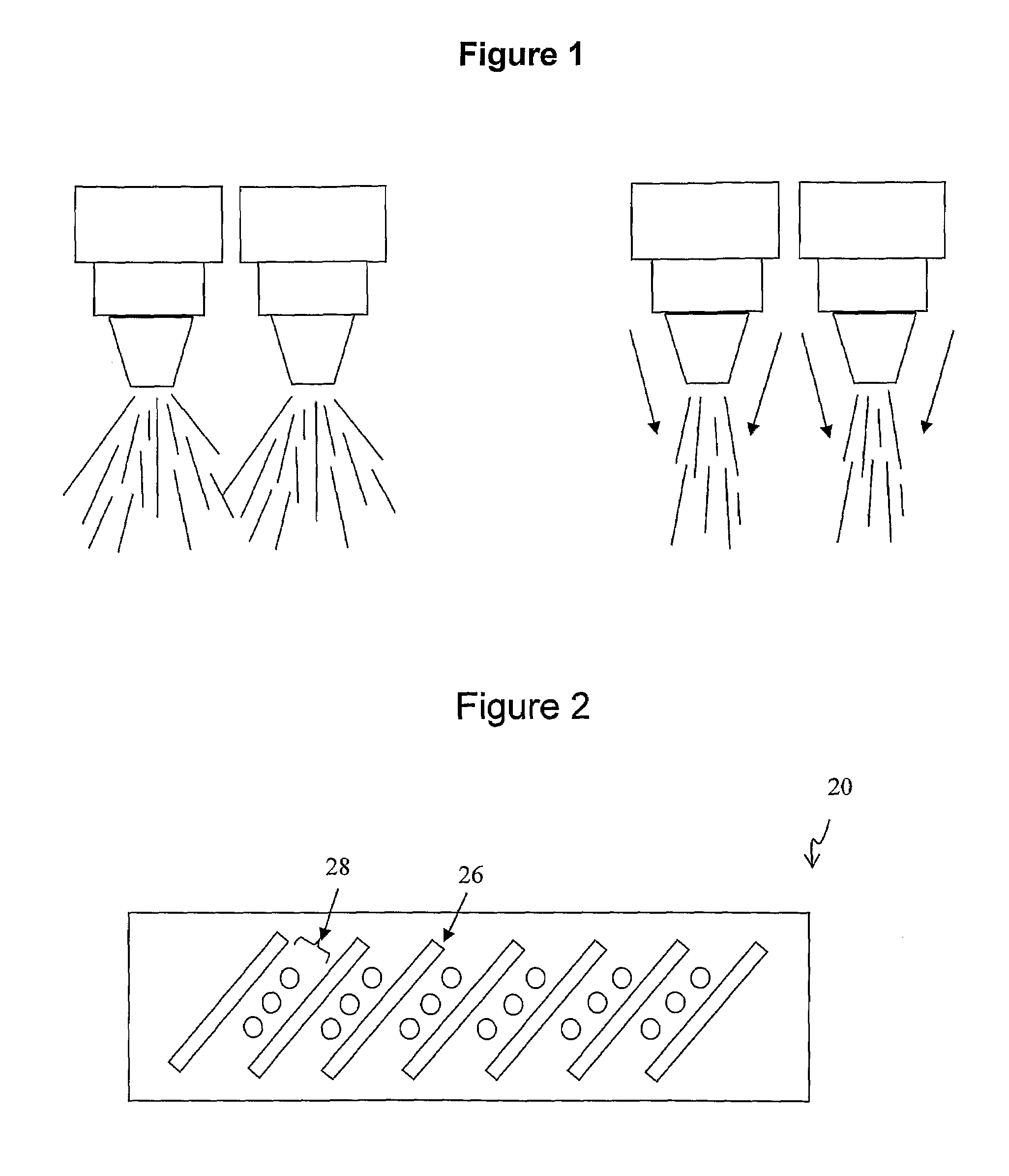
"The present invention is about a method and apparatus for making nanofiber webs. The invention uses a source of process air to affect the spray pattern and quality of fibrillated material expressed from a multi-fluid opening. An ancillary air source, known as a fluid curtain nozzle, is positioned in operative association with the multi-fluid opening. The fluid curtain nozzle is a continuous fluid curtain that acts as a shield to control the spray pattern and temperature of the multi-fluid opening. The invention also contemplates the use of one or more air curtains with various multi-fluid opening configurations, such as slot dies. The technical effects of the invention include improved uniformity of the nanofiber web and reduced interaction or comingling of the fibrous material between adjacent nozzle arrays."

Problems solved by technology

While the physical properties of nanofiber webs are advantageous to a variety of nonwoven markets, commercial products have only reached limited markets due to associated cost.
Laval nozzles are utilized to accelerate the process gas to supersonic speed; however, the process as disclosed has been realized to be prohibitively expensive both in operating and equipment costs.
In this fashion, each nozzle is utilizing a respective supply of primary process air, but lacks an ancillary air source to assist with web formation.

Method used


Image

  • Process and apparatus for forming uniform nanofiber substrates
  • Process and apparatus for forming uniform nanofiber substrates
  • Process and apparatus for forming uniform nanofiber substrates

Examples


Embodiment Construction

[0022]While the present invention is susceptible of embodiment in various forms, there is shown in the drawings, and will hereinafter be described, a presently preferred embodiment of the invention, with the understanding that the present disclosure is to be considered as an exemplification of the invention, and is not intended to limit the invention to the specific embodiment illustrated.

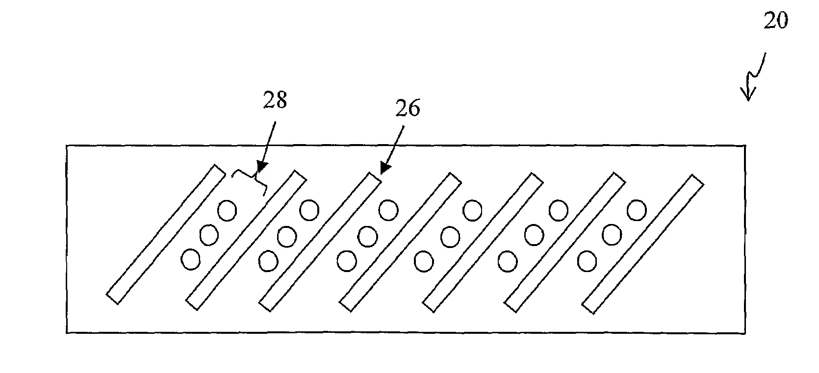
[0023]The method of making nanofiber webs in accordance with the present invention can be practiced in keeping with the teachings of U.S. Pat. Nos. 4,536,361 and 6,183,670, both previously incorporated herein by reference. The present invention further contemplates a method of forming fibrillated nanofibers and nanofiber webs, wherein one embodiment, shown in FIG. 2, includes a die assembly 20 including an array of plural multi-fluid nozzles 28. Each nozzle defines an inner fluid passageway for directing a gas 24, and an outer passageway, wherein the outer passageway surrounds the inner passageway ...


PUM

PropertyMeasurementUnit
diametersaaaaaaaaaa
diametersaaaaaaaaaa
diametersaaaaaaaaaa

Abstract

The present invention is directed to a method and apparatus for making nanofiber webs, wherein a source of process air is utilized to affect the spray pattern and quality of fibrillated material expressed from a die assembly including a multi-fluid opening. Appropriately, the aforementioned process air is defined herein as an alternate or ancillary air source apart from primary process air, which primary air is simultaneously supplied with the molten polymeric material to the fiber forming multi-fluid opening. The ancillary air source of the invention is further distinct from secondary air, which is also known in the art as quenching air. The ancillary air can be described as a continuous fluid curtain of shielding or shaping air.

Description

CROSS-REFERENCE TO RELATED APPLICATION[0001]This application claims the benefit of priority Provisional Application No. 60 / 672,676, filed Apr. 19, 2005. the disclosures of which are incorporated herein by reference.TECHNICAL FIELD[0002]The present invention generally relates to a method and apparatus for making uniform nanofiber webs, and more specifically relates to a method of making uniform nanofiber webs, wherein a source of process air is utilized to affect the spray pattern and quality of fibrillated material as it is expressed from a die assembly including a multi-fluid opening.BACKGROUND OF THE INVENTION[0003]Meltspun technologies, which are known in the art to include the spunbond and meltblown processes, manage the flow of process gases, such as air, and polymeric material simultaneously through a die body to effect the formation of the polymeric material into continuous or discontinuous fiber. In most known configurations of meltblowing nozzles, hot air is provided throug...

Claims


Application Information

Patent Timeline
Patent Type & Authority Patents(United States)
IPC IPC(8): B27N3/00B29C48/345
CPCD01D4/025D04H1/565D01D5/0985D04H1/56
Inventor KRAUSE, TIMFERENCZ, RICKCHHABRA, RAJEEVISELE, OLAFXU, HAN
Owner AVINTIV SPECIALTY MATERIALS INC
Learn More