Aircraft structural components

Inactive Publication Date: 2009-12-08
AIRBUS OPERATIONS LTD
View PDF7 Cites 3 Cited by
  • Summary
  • Abstract
  • Description
  • Claims
  • Application Information

AI Technical Summary

Benefits of technology

[0017]If an opening in a component is sufficiently small then the structural considerations are rather different and the demands less severe. The present invention is of particular advantage in a case where the opening in the structural component has a smallest dimension greater than 25mm and/or an area greater than 600mm2; usually the opening will have an area greater than 104mm2 and the second composite fibre and matrix material will extend across a width greater than 400mm.
[0018]The i

Problems solved by technology

A particular issue arises if it is desired to place a manhole in a lower wing skin formed of a composite fibre arid matrix material.
If, however, a manhole were to be placed in the lower wing skin formed of such a composite material, then, when during flight the lower wing skin is subjected to tension, especially high stresses would arise at the edge of the manhole, those stresses being accentuated in any region of damage to

Method used


Image

  • Aircraft structural components
  • Aircraft structural components

Examples


Embodiment Construction

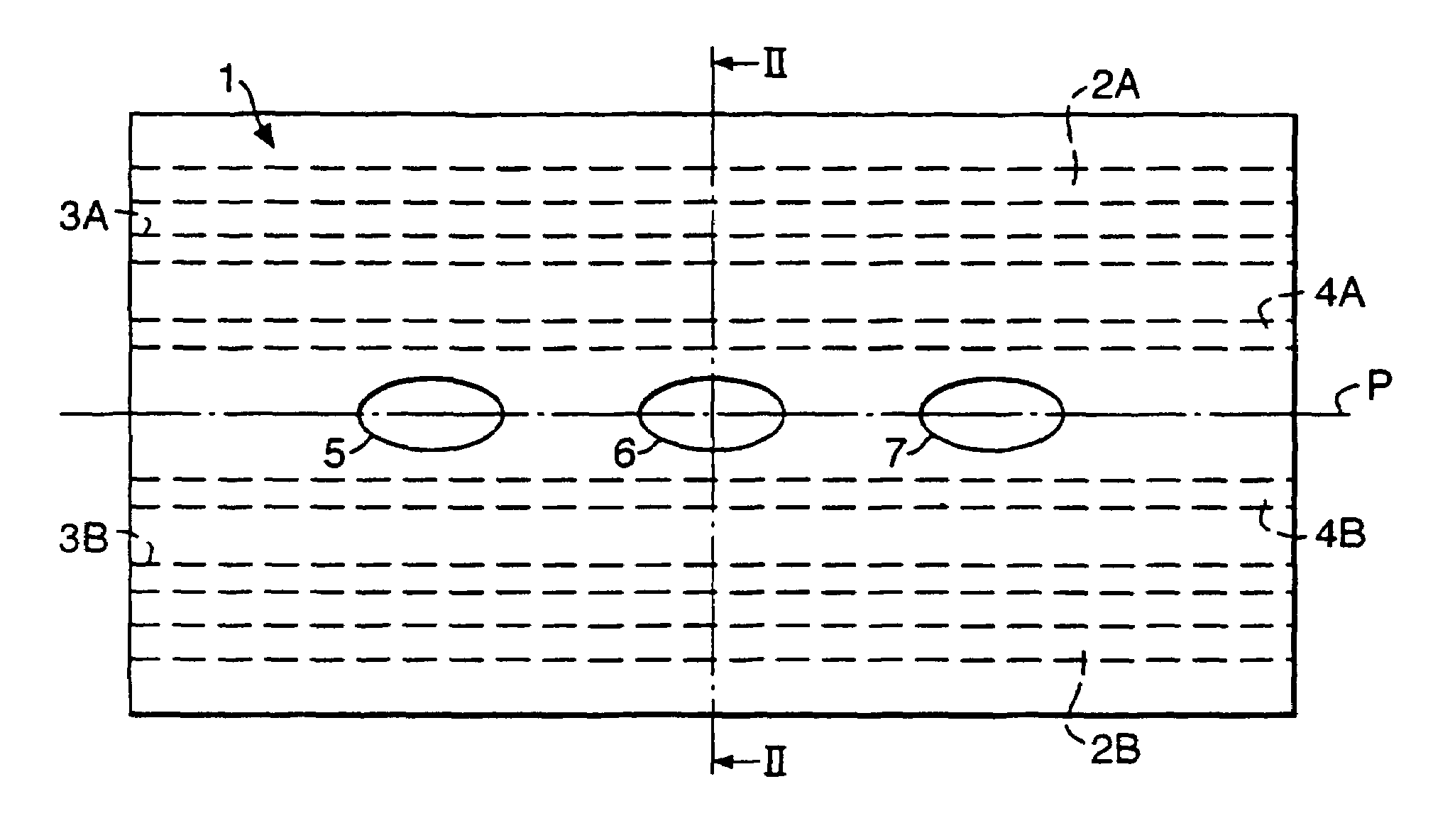
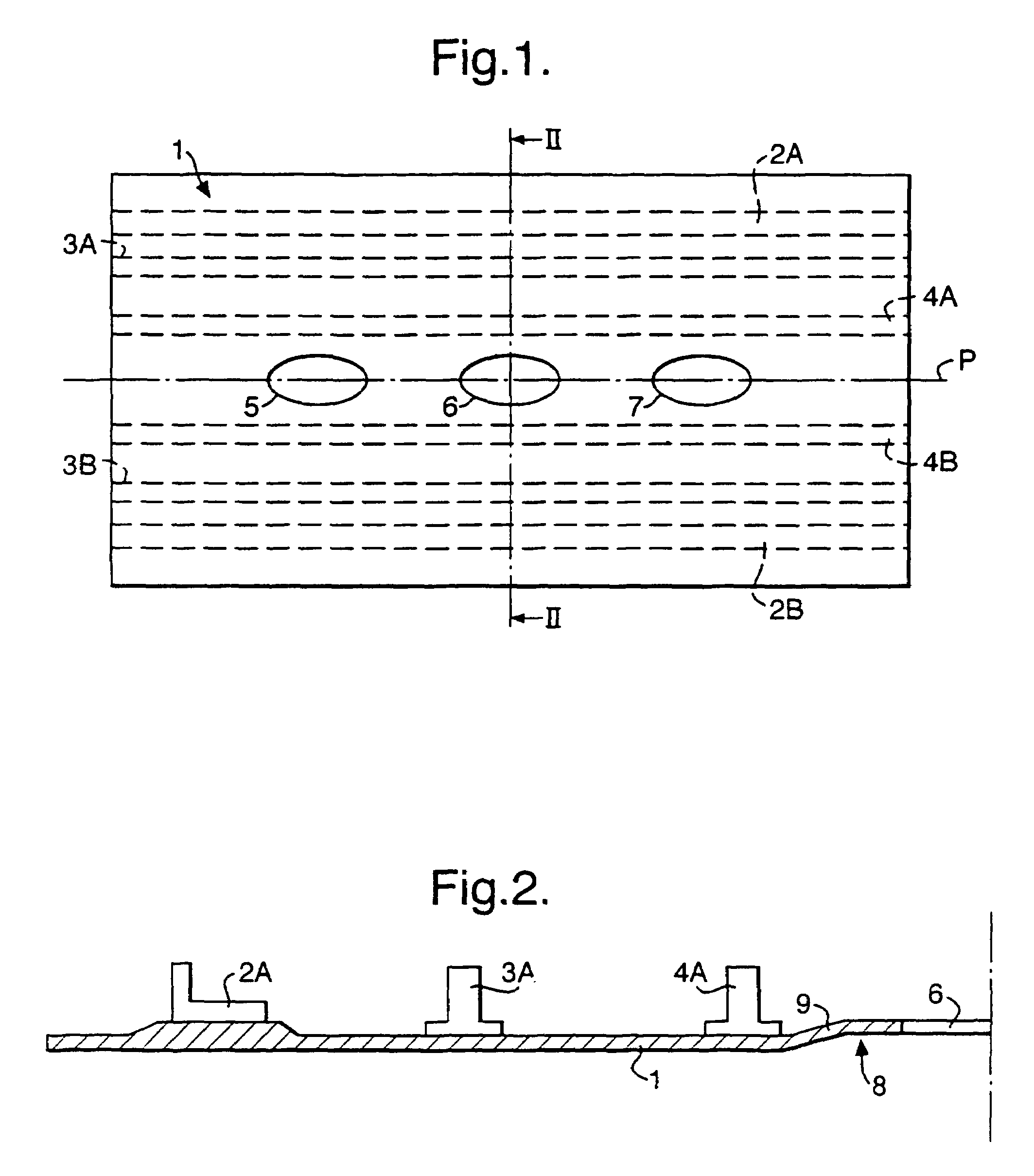
[0024]In the drawings the wing skin 1 is shown as flat, but it will be understood that in practice the wing skin will incorporate an aerodynamic curve, the radius of which would typically be of the order of 6 m.

[0025]The wing structure shown in FIGS. 1 and 2 is conventional and in this example, comprises a pair of spars 2A and 2B in the region of the leading and trailing edges of the wing and stringers 3A and 3B and 4A and 4B extending along the wing skin inside the spars 2A and 2B. No ribs are shown in FIGS. 1 and 2 but it should be understood that there may also be one or more ribs present. As will be understood, the wing structure of the example shown in FIGS. 1 and 2 is symmetrical about a longitudinal vertical plane marked P in FIG. 1. Suffix A is used to designate parts on one side of the plane P and suffix B to designate the corresponding part on the opposite side of the plane P.

[0026]Along the length of the wing structure shown in FIGS. 1 and 2 three manholes 5, 6 and 7, eac...


PUM


Abstract

A structural component such as a wing skin for an aircraft is formed generally of a first composite fiber and matrix material exhibiting a first tensile modulus in respect of tensile stress and a first tolerance of strain resulting from such stress. One or more openings are provided in the component and the material of a portion of the component bounding the opening(s) is a second composite fiber and matrix material. The second material exhibits a second tensile modulus in respect of tensile stress that is smaller than the first tensile modulus of the first material and a second tolerance of strain resulting from such stress that is greater than the first tolerance of strain of the first material.

Description

[0001]This is the U.S. national phase of international application PCT / GB02 / 03202 filed Jul. 11,2002 which designate the U.S., the entire contents of which are hereby incorporated by reference.BACKGROUND OF THE INVENTION[0002]1. Field of the Invention[0003]This invention relates generally to the construction of structural components of an aircraft. The invention has particular significance to the behaviour of structural components when subjected to tensile stress and is therefore especially relevant to structural components that are subjected to tensile stress during normal use. The invention is particularly, but not exclusively, directed to a lower wing skin for an aircraft, and to an aircraft wing structure and an aircraft including such a lower wing skin. As is well known, lower wing skins of aircraft are subjected to tensile stress during normal flight conditions.[0004]2. Discussion of Prior Art[0005]It is commonly desired to provide openings in wing skins, for example, to enabl...

Claims


Application Information

Patent Timeline
IPC IPC(8): B32B3/10B64C1/14B64C3/26
CPCB64C1/1446B64C3/26Y10T428/24273
Inventor GAITONDE, JOHN M.
Owner AIRBUS OPERATIONS LTD
Why Eureka
Try Eureka