Apparatus and method for controlling ion beam

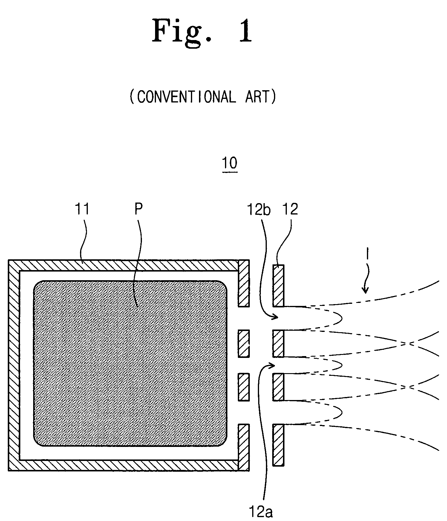
a technology of apparatus and ion beam, which is applied in the direction of mass spectrometers, nuclear engineering, machines/engines, etc., can solve the problems of increasing difficulty in controlling process window capable of changing a process condition may be considerably limited, and the difficulty of fabricating an extraction electrode b>12, so as to improve the uniformity of ion beam distribution

Active Publication Date: 2009-12-08
SAMSUNG ELECTRONICS CO LTD
View PDF21 Cites 7 Cited by
  • Summary
  • Abstract
  • Description
  • Claims
  • Application Information

AI Technical Summary

Benefits of technology

[0010]Example embodiments may provide an apparatus for controlling an ion beam. The apparatus may include at least one extraction electrode disposed in a path of an ion beam. The at least one extraction electrode may include a plurality of sub-grids. Accordingly, a divergence of the ion beam may be easily controlled and / or the uniformity of the ion beam may be improved by controlling the ion beam corresponding to a position of the sub-grids.
[0020]According to an example embodiment, the beam controlling extraction electrode may be spaced from the first extraction electrode most adjacent to the ion source and / or may be located between the first extraction electrode and the final extraction electrode. A positive potential may be applied to the first extraction electrode and / or a negative potential may be applied to the beam controlling extraction electrode. Accordingly, flux distribution of the ion beam may be controlled to improve the uniformity of the ion beam.
[0029]According to an example embodiment, the ion beam may be measured to obtain a two-dimensional distribution of the ion beam and / or form an extraction electrode consisting of a plurality of sub-grids having a two-dimensional shape corresponding to the distribution of the ion beam. The extraction electrode formed reflecting the ion beam distribution may be attached to an apparatus for controlling the ion beam and a desired, or alternatively, a proper potential may be applied to the plurality of sub-grids to improve the uniformity of the ion beam distribution.

Problems solved by technology

However, it may be difficult to fabricate an extraction electrode 12 with spatially different diameters for extraction holes.
Accordingly, a process window capable of changing a process condition may be considerably limited.
In conventional semiconductor devices, because a size of the extraction electrode has been increased according to an increase in a wafer size, the aforementioned method may increasingly have difficulty in controlling the uniformity of the ion beam.

Method used


Image

  • Apparatus and method for controlling ion beam
  • Apparatus and method for controlling ion beam
  • Apparatus and method for controlling ion beam

Examples


Embodiment Construction

[0038]Example embodiments will now be described more fully hereinafter with reference to the accompanying drawings. Embodiments may, however, be in many different forms and should not be constructed as limited to the example embodiments set forth herein. Rather, these example embodiments are provided so that this disclosure will be thorough and complete, and will fully convey the scope to those skilled in the art. In the drawings, the thicknesses of layers and regions may be exaggerated for clarity.

[0039]It will be also understood that, although the terms first, second, third, and the like may be used herein to describe various regions, voltages, and the like, these regions and voltages should not be limited by these terms. These terms are only used to distinguish one region and voltage from another region and voltage.

[0040]It will be understood that when a component is referred to as being “on,”“connected to” or “coupled to” another component, it can be directly on, connected to or...


PUM


Abstract

An apparatus and / or method for controlling an ion beam may be provided, and / or a method for preparing an extraction electrode for the same may be provided. In the apparatus, a plurality of extraction electrodes may be disposed in a path of an ion beam. At least one extraction electrode may include a plurality of sub-grids.

Description

PRIORITY STATEMENT[0001]This U.S. non-provisional patent application claims the benefit of priority under 35 U.S.C. §119 to Korean Patent Application No. 10-2006-11845, filed on Feb. 7, 2006, the entire contents of which are hereby incorporated herein in their entirety by reference.BACKGROUND[0002]1. Field[0003]Example embodiments relate to an apparatus for fabricating a semiconductor device, and for example, to an apparatus and / or a method for controlling an ion beam, and / or to a method for preparing an extraction electrode for the same.[0004]2. Description of Related Art[0005]An ion beam apparatus using a plasma as an ion source has been utilized in a processing apparatus for a semiconductor device. In the ion beam apparatus, a plurality of extraction electrodes in which a plurality of extraction holes may be formed may be disposed at an extraction terminal of the ion source. A voltage may be applied between the extraction electrodes to extract an ion beam from the ion source.[000...

Claims


Application Information

Patent Timeline
Patent Type & Authority Patents(United States)
IPC IPC(8): G21K1/08H01J1/36H01J1/46
CPCH01J27/024H01J37/08H01J2237/31701H01J2237/3151H01J2237/061B43L19/005
Inventor HWANG, SUNG-WOOKLEE, DO-HAINGSHIN, CHUL-HOSUN, JONG-WOO
Owner SAMSUNG ELECTRONICS CO LTD
Why Eureka
Try Eureka