Cooling device for electric apparatus mounted on vehicle

a technology for cooling devices and electric appliances, which is applied in the direction of electric devices, hybrid vehicles, battery/fuel cell control arrangements, etc., can solve the problems of difficult to freely provide an exhaust duct in the hybrid vehicle for mounting a voluminous assembled battery, and the interior of the vehicle is exhausted in a single direction, so as to avoid a local temperature rise and without requiring a large space

Inactive Publication Date: 2009-12-15
TOYOTA JIDOSHA KK
View PDF39 Cites 37 Cited by
  • Summary
  • Abstract
  • Description
  • Claims
  • Application Information

AI Technical Summary

Benefits of technology

[0013]The present invention has been made to solve the above-described problems. An object of the present invention is to provide a cooling device for an electric apparatus mounted on a vehicle, the cooling device being capable of avoiding a local temperature rise in the vehicle interior, without requiring a large space.

Problems solved by technology

Furthermore, if the local temperature rise occurs at the lower portion of the rear seat, the exhaust airflow impinges upon the feet of a passenger / passengers sitting on the rear seat (on the right side or the left side, or the both sides), or warms the feet (uncomfortable feeling occurs).
However, air is exhausted into the vehicle interior in a single direction.
On the other hand, it is difficult to freely provide an exhaust duct in the hybrid vehicle for mounting a voluminous assembled battery, which has not been mounted on the conventional vehicle that relies solely on the internal combustion engine as its driving source.

Method used


Image

  • Cooling device for electric apparatus mounted on vehicle
  • Cooling device for electric apparatus mounted on vehicle
  • Cooling device for electric apparatus mounted on vehicle

Examples


first embodiment

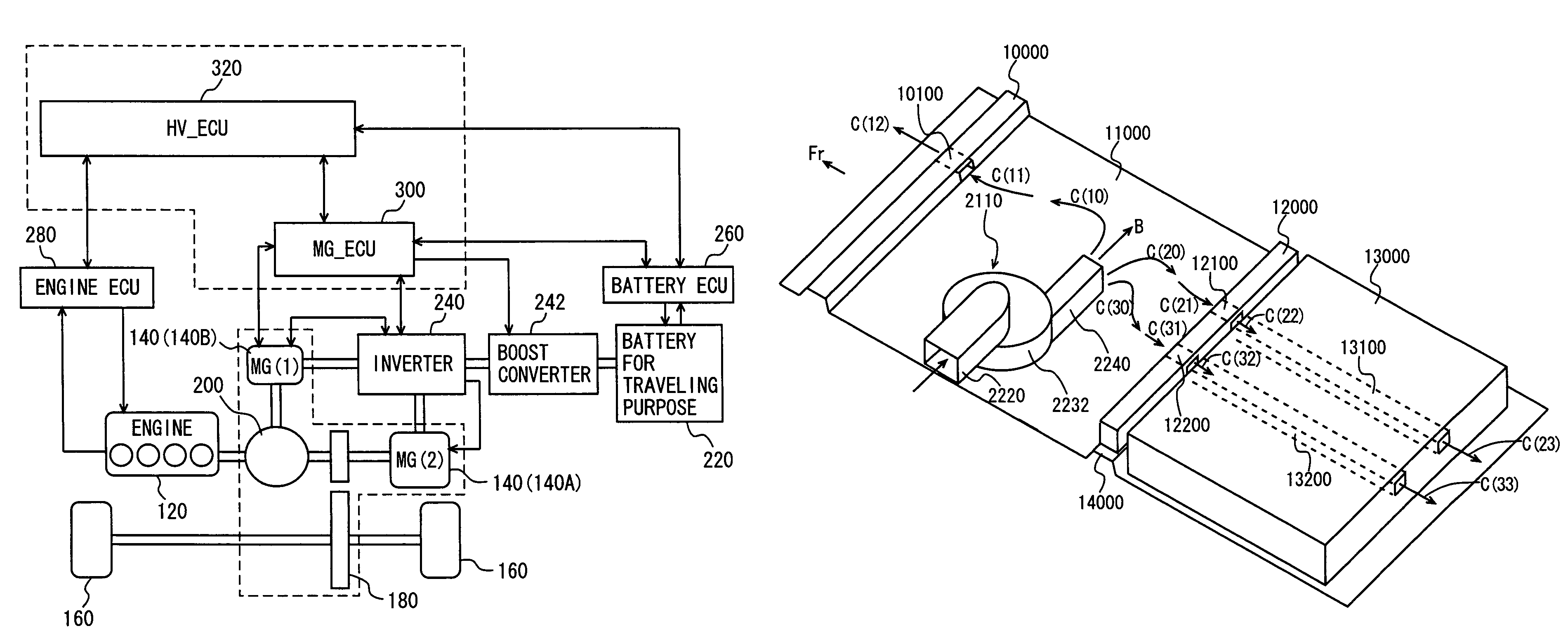
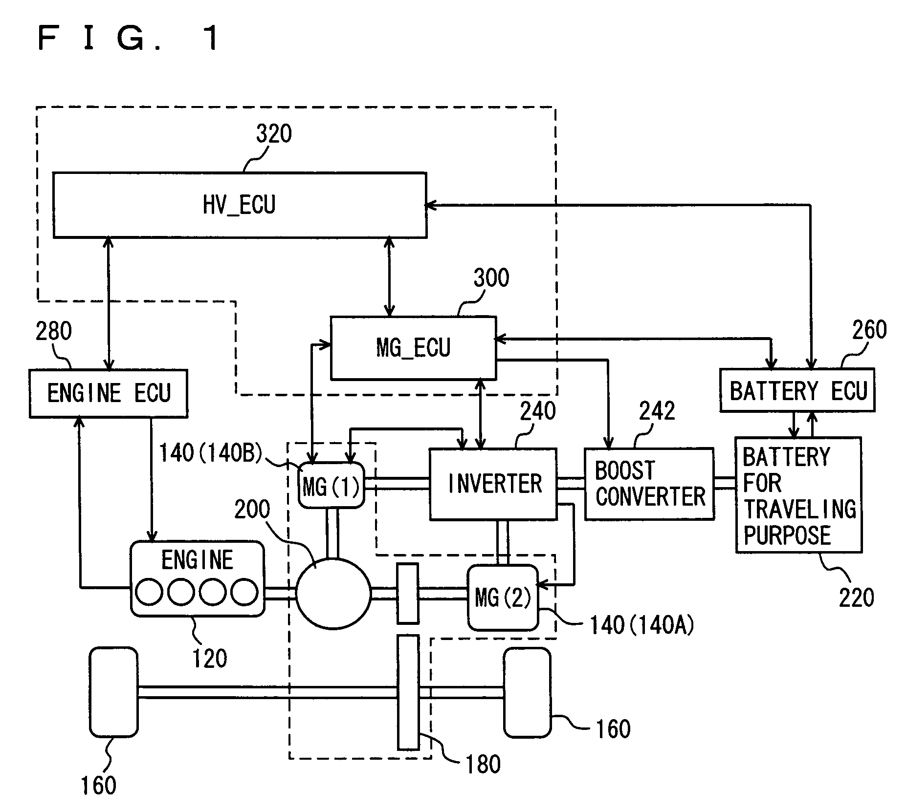
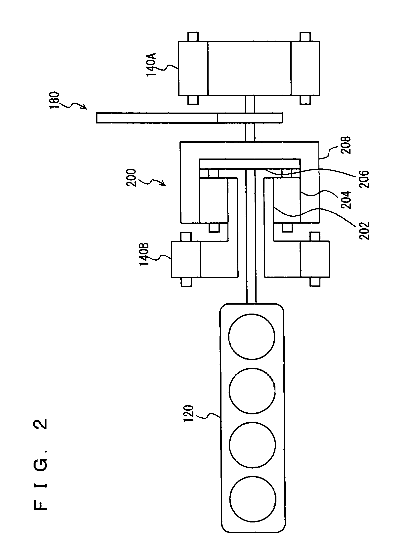
[0037]With reference to FIG. 1, there will be described a control block diagram of the entire hybrid vehicle including a cooling device according to a first embodiment of the present invention. Note that the present invention is not limited to the hybrid vehicle shown in FIG. 1. The present invention is not limited to the hybrid vehicle as long as an internal combustion engine (hereinafter referred to as an engine for explanation), such as a gasoline engine that serves as a motive power source, functions as a driving source (traveling source) for causing the vehicle to travel, and also functions as a driving source for a generator. Furthermore, the present invention is not limited to the hybrid vehicle as long as the engine and the motor generator serve as driving sources, and the vehicle can travel by motive power of the motor generator (irrespective of whether the engine is stopped or not). The present invention may be applied to a hybrid vehicle mounted with a battery for traveli...

second embodiment

[0082]With reference to FIG. 8, there will be described a cooling device according to a second embodiment of the present invention. Note that the present embodiment has the same configurations as those of the first embodiment described above with regard to FIGS. 1-5. Therefore, the detailed description thereof will not be repeated here. Furthermore, in the top view shown in FIG. 8, the same configurations as those in FIG. 7 above are provided with the same reference characters, and have the same functions as well. Therefore, the detailed description thereof will not be repeated here.

[0083]FIG. 8 is a top view that corresponds to FIG. 7 in the first embodiment described above. The cooling device according to the present embodiment is of the so-called draft type as well, in which an electric-powered battery cooling fan is provided in an air exhaust path. Therefore, air is exhausted in the direction shown by arrow B in FIG. 8.

[0084]The cooling device according to the present embodiment...

third embodiment

[0097]With reference to FIG. 9, a cooling device according to a third embodiment of the present invention will be described. Note that the present embodiment has the same configurations as those of the first embodiment described above with regard to FIGS. 1-5, as in the second embodiment. Therefore, the detailed description thereof will not be repeated here. Furthermore, in the top view shown in FIG. 9, the same configurations as those in FIG. 7 described above are provided with the same reference characters, and have the same functions as well. Therefore, the detailed description thereof will not be repeated here.

[0098]FIG. 9 is a top view that corresponds to FIG. 7 in the first embodiment described above and FIG. 8 in the second embodiment described above. The cooling device according to the present embodiment is of the so-called draft type as well, in which an electric-powered battery cooling fan is provided in an air exhaust path. Therefore, air is exhausted in the direction of ...


PUM

PropertyMeasurementUnit
voltageaaaaaaaaaa
output voltageaaaaaaaaaa
temperatureaaaaaaaaaa

Abstract

Exhaust air from an electric-powered battery cooling fan which draws in an exhaust airflow from a battery for traveling purpose is diffused in a direction to a ventilating opening provided in a first cross member, as shown by an arrow C (10), an arrow C (11), and an arrow C (12), in a direction to a first ventilating opening provided in a cushioning material and a first ventilating duct provided in a cushioning material, as shown by an arrow C (20), an arrow C (21), an arrow C (22), and an arrow C (23), and in a direction to a second ventilating opening provided in the cushioning material and a second ventilating duct provided in the cushioning material, as shown by an arrow C (30), an arrow C (31), an arrow C (32), and an arrow C (33). With such a configuration, a local temperature rise in a vehicle interior is avoided even though the exhaust airflow flows from the battery for traveling purpose, without the need of a large space.

Description

[0001]This nonprovisional application is based on Japanese Patent Application No. 2007-109683 filed with the Japan Patent Office on Apr. 18, 2007, the entire contents of which are hereby incorporated by reference.BACKGROUND OF THE INVENTION[0002]1. Field of the Invention[0003]The present invention relates to a cooling device for an electric apparatus mounted on a vehicle, and particularly relates to a cooling device for a power storage mechanism (a battery, a capacitor, and others), a PCU (Power Control Unit), and others used for an electric vehicle (EV), a hybrid vehicle (HV), and others.[0004]2. Description of the Background Art[0005]Each of an electric vehicle, a hybrid vehicle, and a fuel cell vehicle, which obtains driving force for the vehicle from an electric motor, is mounted with a power storage mechanism (a secondary battery (also referred to as a battery), a capacitor, and others). As to the electric vehicle, electric power stored in the power storage mechanism is used to...

Claims


Application Information

Patent Timeline
Patent Type & Authority Patents(United States)
IPC IPC(8): B60K11/06B60K1/04B60R16/04B62D25/20H01M10/60H01M10/613H01M10/617H01M10/625H01M10/633H01M10/637H01M10/6556H01M10/6563H01M10/663
CPCB60K1/04B60L3/0046B60L3/0053B60L11/123B60L11/14B60L11/1874H01M10/5004H01M10/5016H01M10/5067Y02T90/34B60L2240/36H01M10/5032H01M10/5073H01M10/5095Y02T10/6217Y02T10/7005Y02T10/7022Y02T10/705Y02T10/7077B60K2001/005B60L50/16B60L50/61B60L58/13B60L58/26H01M10/613H01M10/625H01M10/647H01M10/6563H01M10/6566H01M10/663Y02E60/10Y02T10/62Y02T10/70Y02T10/7072Y02T90/40
Inventor KUBO, MASAHIKO
Owner TOYOTA JIDOSHA KK
Why Eureka
Try Eureka