Thin film magnetic head having heating element

a technology of heating element and magnetic head, which is applied in the direction of head with metal sheet core, data recording, instruments, etc., can solve the problems of difficult control in such a way, deterioration of recording and playback characteristics, damage to recording medium, etc., and achieves the prevention of local temperature increase in the electrode lead, easy manufacturing process, and reduced protrusion of the periphery of the element portion

Active Publication Date: 2007-11-29
TDK CORPARATION
View PDF28 Cites 3 Cited by
  • Summary
  • Abstract
  • Description
  • Claims
  • Application Information

AI Technical Summary

Benefits of technology

[0018] The pair of electrode leads may be formed from the same material as the material for the heating element are disposed integrally with the heating element. When the heating element and the pair of electrode leads are formed simultaneously, that is, in the same step, the manufacturing process is carried out easily.
[0019] According to an exemplary embodiment of the present invention, since the pair of electrode leads of the heating element include the overlapping regions, which overlap with the upper shield layer in a lamination direction, and heat dissipation regions, which are extended from the overlapping regions ...

Problems solved by technology

However, when the element portion is intended to protrude toward the recording medium side, the periphery of the element portion is also thermally expanded and, therefore, it is difficult to control in such a way that the protrusion of the element portion becomes the largest.
In the case where the amount of protrusion of the periphery of the element portion is larger than that of the element portion, the periphery of the element portion is brought into contact with the recording medium prior to the contact of the element portion, and, the...

Method used


Image

  • Thin film magnetic head having heating element
  • Thin film magnetic head having heating element
  • Thin film magnetic head having heating element

Examples


first embodiment

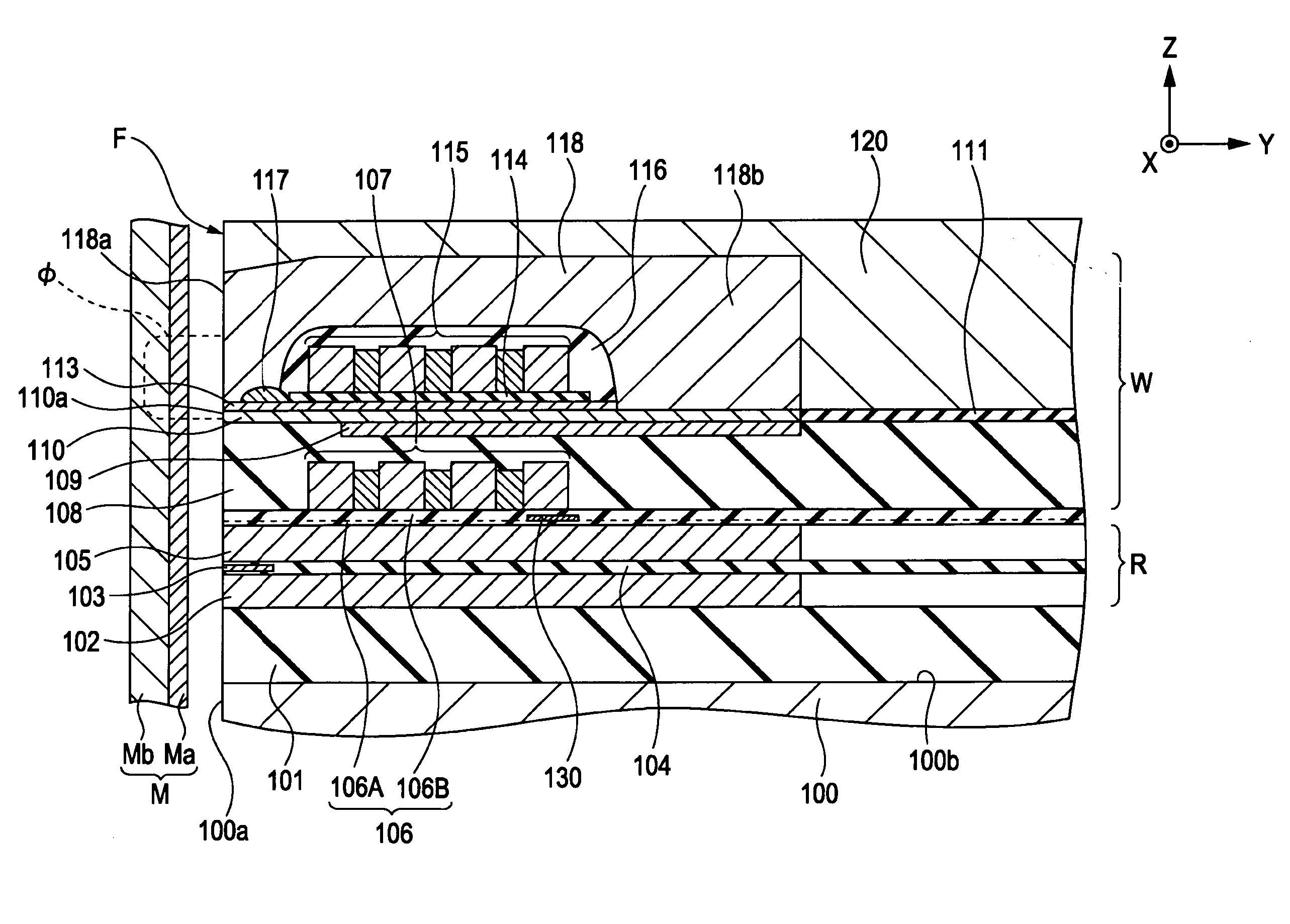
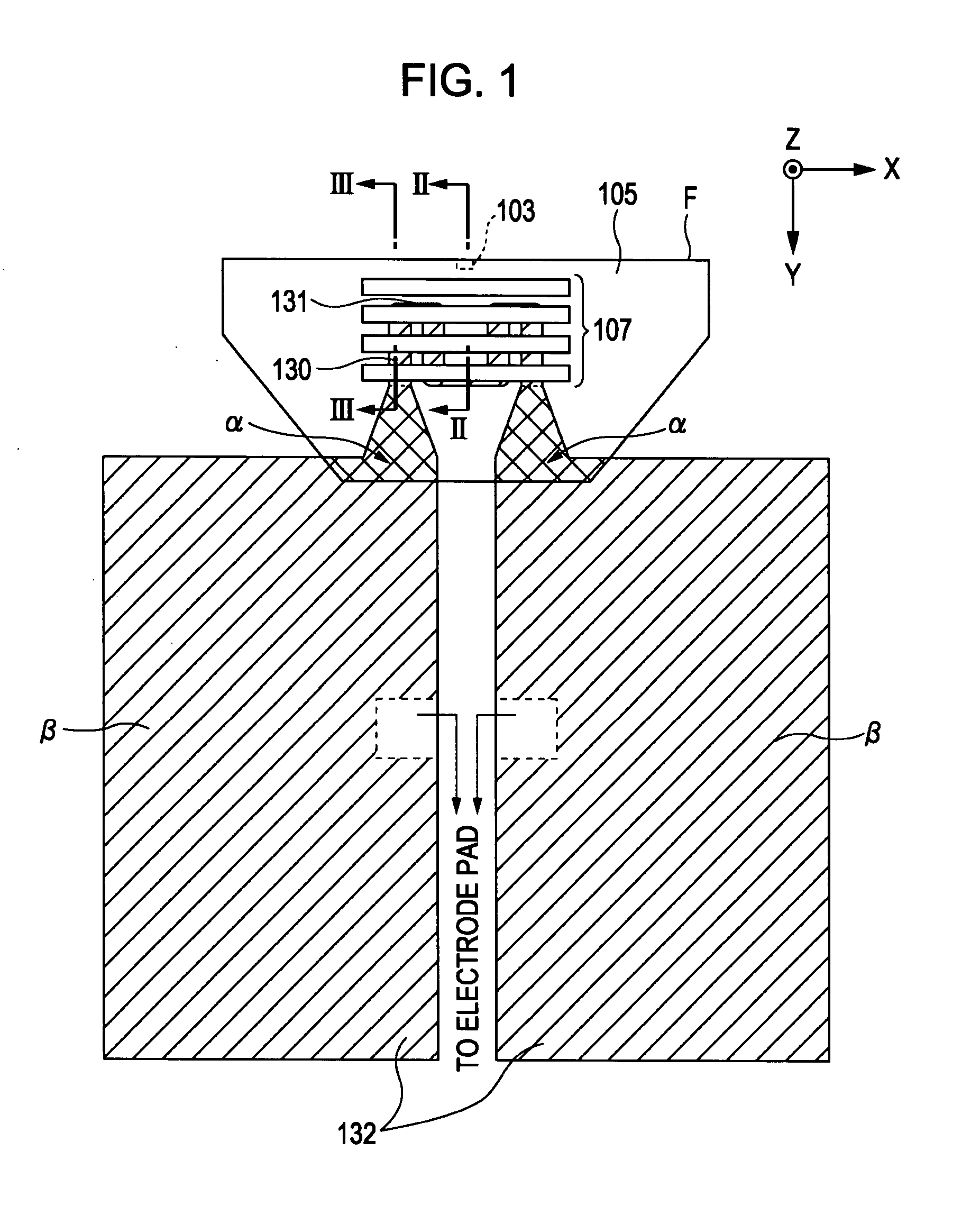
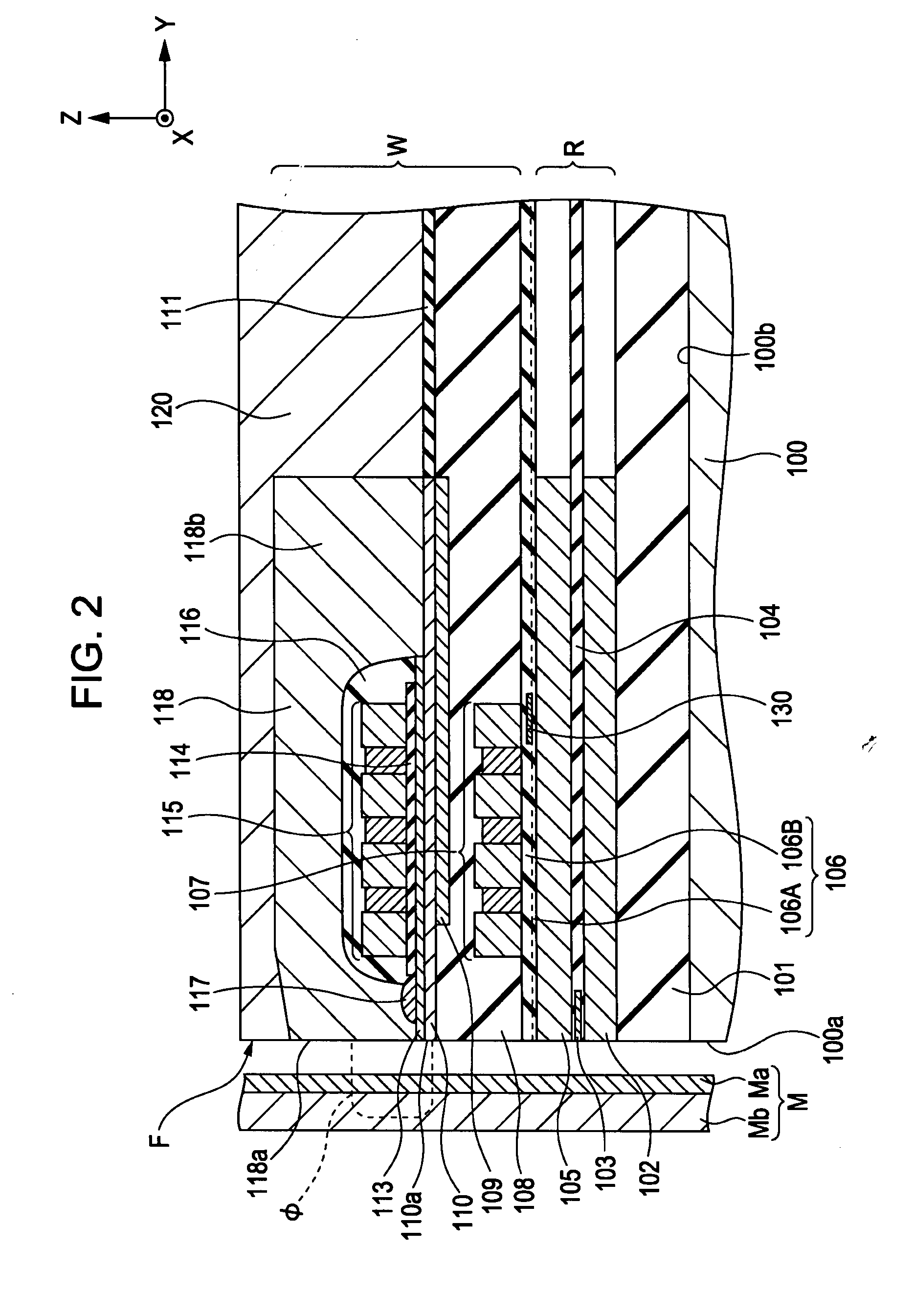
[0028]FIG. 1 to FIG. 3 show a thin film magnetic head according to the present invention. FIG. 1 is a plan view showing the structure of the thin film magnetic head, viewed from above lower layer coils 107. FIG. 2 is a sectional view of a section taken along a line II-II shown in FIG. 1. FIG. 3 is a sectional view of a section taken along a line III-III shown in FIG. 1.

[0029] The thin film magnetic head is a perpendicular magnetic recording head including a playback portion R and a recording portion W, each produced by laminating thin films, on a trailing-side end surface 100b of a slider 100. The playback portion R reads magnetic information from a recording medium M through the use of a magnetoresistance effect. The recording portion W gives a perpendicular magnetic field Φ to the recording medium M and, thereby, magnetize a hard film Ma of the recording medium M in a perpendicular direction so as to perform a recording operation.

[0030] The recording medium M includes the hard fi...

second embodiment

[0045]FIG. 4 to FIG. 6 show a thin film magnetic head according to the present invention. FIG. 4 is a plan view showing the structure of the thin film magnetic head, viewed from above lower layer coils 107. FIG. 5 is a sectional view of a section taken along a line V-V shown in FIG. 4. FIG. 6 is a sectional view of a section taken along a line VI-VI shown in FIG. 4.

[0046] The thin film magnetic head is a perpendicular magnetic recording head including a playback portion R and a recording portion W, each produced by laminating thin films, on a trailing-side end surface 100b of a slider 100. The playback portion R reads magnetic information from a recording medium M through the use of a magnetoresistance effect. The recording portion W gives a perpendicular magnetic field Φ to the recording medium M and, thereby, magnetize a hard film Ma of the recording medium M in a perpendicular direction so as to perform a recording operation.

[0047] The recording medium M includes the hard film M...


PUM


Abstract

A thin film magnetic head is provided, in which the amount of protrusion in the periphery of an element portion can be reduced or a local temperature increase of electrode leads of a heating element can be prevented. The thin film magnetic head includes a playback element disposed between lower and upper shield layers, a recording element laminated on the upper shield layer, a heating element which is disposed below a coil layer and which generates heat to allow the playback element to protrude toward the recording medium side through thermal expansion, and a pair of electrode leads including overlapping regions, which are in contact with rear ends of the heating element and which overlap with the upper shield layer, and heat dissipation regions. Furthermore, connection wiring portions of the pair of electrode leads are disposed in a region sandwiched between the upper shield layer and a magnetic layer.

Description

[0001] This application claims the benefit of Japanese Patent Application No. 2006-139899, filed on May 19, 2006 and Japanese Patent Application No. 2006-337928, filed on Dec. 15, 2006, the contents of which are incorporated herein by reference. BACKGROUND OF THE INVENTION [0002] 1. Field of the Invention [0003] The present invention relates to a thin film magnetic head in which the amount of flying is controlled by locally protruding an element portion toward a recording medium side through thermal expansion. [0004] 2. Description of the Related Art [0005] A thin film magnetic head is provided with at least one playback element, which includes a multilayer film exhibiting a magnetoresistance effect between a lower shield layer and an upper shield layer and which reads magnetic information from a recording medium on the basis of the change in resistance of the multilayer film. The thin film magnetic head also includes a recording element which includes a pair of magnetic core layers...

Claims


Application Information

Patent Timeline
IPC IPC(8): G11B5/147G11B5/33
CPCG11B5/1278G11B5/3136G11B5/6064G11B5/3967G11B5/314
Inventor KOBAYASHI, KIYOSHIMORITA, SUMIHITOOTSUKA, TOMOO
Owner TDK CORPARATION
Why Eureka
Try Eureka