Small soy sauce fermentation tank

A fermenter and soy sauce technology, applied in bioreactor/fermenter combination, specific-purpose bioreactor/fermenter, biochemical instruments, etc., can solve the problem of inaccurate temperature detection, improve accuracy and speed up , the effect of enhancing controllability

Inactive Publication Date: 2020-11-03
冯步迎
View PDF1 Cites 3 Cited by
  • Summary
  • Abstract
  • Description
  • Claims
  • Application Information

AI Technical Summary

Problems solved by technology

The soy sauce fermenter in the above patent has the following disadvantages: when the temperature sensor is used to measure the temperature of materials in different positions, when the temperature sensor is moved, a large amount of materials in the original position adhere to the outer wall and move together to the place to be detected, resulting in inaccurate temperature detection.

Method used


Image

  • Small soy sauce fermentation tank
  • Small soy sauce fermentation tank
  • Small soy sauce fermentation tank

Examples


Embodiment 1

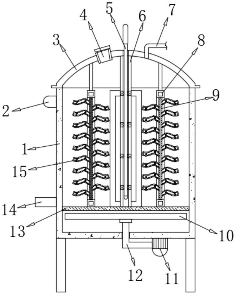
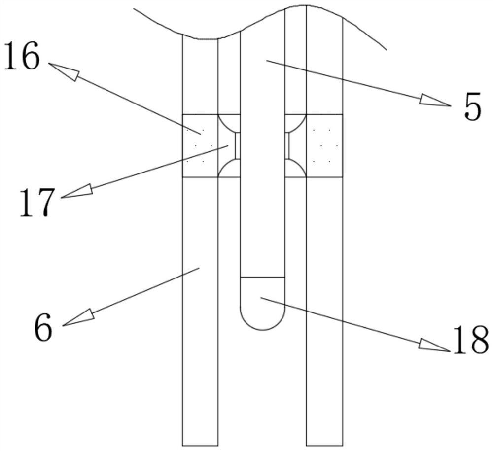
[0029] refer to Figure 1-5 , a small soy sauce fermentation tank, comprising a tank body 1, the top of the tank body 1 is connected with a top cover 3 by fastening bolts, and the bottom of the inner wall of the tank body 1 is connected with a sieve plate 13 by fastening bolts, and the sieve plate 13 A distributor 10 is provided at the bottom, and an air inlet pipe 12 is provided at the bottom of the distributor 10, a slag outlet 14 is plugged into one side of the outer wall of the tank body 1, and a feed inlet 4 is provided on one side of the top outer wall of the top cover 3, The top outer wall of the top cover 3 is plugged with an air outlet pipe 7, and the top inner wall of the top cover 3 is connected with two fixed rods 6 by fastening bolts, and the two fixed rods 6 are connected with evenly distributed spacer rings 16 by fastening bolts , the circumferential inner wall of the limit ring 16 is connected with a scraper ring 17 by fastening bolts, the top of the top cover ...

Embodiment 2

[0038] refer to Image 6 , a warp knitting machine pulling and winding device for weaving plastic nets. Compared with Embodiment 1, the bottom of the inner wall of the tank body 1 is provided with a limited groove, and both sides of the distributor 10 pass through tight The fixed bolts are connected to the limit block, and the outer diameter of the limit block is compatible with the inner diameter of the limit groove. Both sides of the outer wall of the bottom of the tank body 1 are connected with drive motors 22 by fastening bolts, and the output of the two drive motors 22 The shafts are all connected with drive gears 21 by fastening bolts, and the circumference of the bottom of the distributor 10 is connected with a gear ring 23 by fastening bolts, and the circumferences of the two drive gears 21 and the peripheral outer walls of the gear ring 23 mesh with each other.

[0039] Working principle: When in use, the gear ring 23 and the distributor 10 can be driven to rotate by ...


PUM


Abstract

The invention discloses a small soy sauce fermentation tank. The small soy sauce fermentation tank comprises a tank body, wherein a top cover is arranged at the top of the tank body, a sieve plate isarranged at the bottom of the circumferential inner wall of the tank body, a distributor is arranged at the bottom of the sieve plate, an air inlet pipe is arranged at the bottom of the distributor, and a residue outlet is inserted into the outer wall of one side of the tank body; a feeding opening is formed in one side of the outer wall of the top of the top cover, an air outlet pipe is insertedinto the outer wall of the top of the top cover, and two fixing rods are arranged on the inner wall of the top of the top cover. The height of a temperature sensor is adjusted by pulling an extensionrod to measure the temperature of materials at different horizontal positions, and when the extension rod is pulled, the circumferential inner wall of a material scraping ring makes contact with the extension rod and the circumference of the temperature sensor to conduct scraping. Therefore, inaccurate temperature detection caused by the fact that a large number of materials at original positionsare adhered to the outer wall of the temperature sensor and move to a to-be-detected position when the temperature sensor moves is avoided, and temperature detection accuracy is improved.

Description

technical field [0001] The invention relates to the technical field of soy sauce fermentation, in particular to a small soy sauce fermentation tank. Background technique [0002] The brewing methods of soy sauce are mainly divided into two categories: high-salt dilute state brewing method and low-salt solid-state fermentation method. Among them, the flavor of soy sauce brewed by solid-state fermentation is poor, mainly because the heat transfer and mass transfer effect of the solid substrate is worse than that of the liquid substrate, resulting in a higher temperature of the material layer in the solid-state fermentation process, resulting in the passivation and deactivation of many enzymes at low temperature. It cannot play a role, and at the same time, beneficial microorganisms such as yeast and lactic acid bacteria cannot grow and metabolize, and can only complete the hydrolysis of starch and protein, which cannot create conditions for the generation of rich nutrients and...

Claims


Application Information

Patent Timeline
IPC IPC(8): C12M1/34C12M1/38C12M1/40C12M1/00A23L27/50
CPCA23L27/50C12M21/18C12M27/00C12M39/00C12M41/22
Inventor 冯步迎
Owner 冯步迎
Why Eureka
Try Eureka