Conveyor system

a conveyor system and workpiece technology, applied in mechanical conveyors, packaging, manufacturing tools, etc., can solve the problems of no means for repositioning the workpiece, significantly reducing the recovery of lumber, and slow and time-consuming manual rotation of the workpi

Active Publication Date: 2009-12-15
USNRKOCKUMS CANCAR +1
View PDF36 Cites 7 Cited by
  • Summary
  • Abstract
  • Description
  • Claims
  • Application Information

AI Technical Summary

Benefits of technology

[0009]It is an object of the invention to provide a continuous sharp chain conveyor system for transporting a workpiece such that span distances between successive conveyors are eliminated.
[0010]It is another object of the invention to provide a sharp chain conveyor system having a single conveyor to reduce the length of the system.
[0011]It is another object of the invention to provide a means to elevate the workpiece from the sharp chain conveyor such that the position of the workpiece may be adjusted at anytime while the workpiece is transported down the sharp chain conveyor system.
[0012]It is a further object of the invention to provide a continuous means to rotate the workpiece such that the optimized position of the workpiece may be maintained while the workpiece is transported down the sharp chain conveyor system.
[0016]Pairs of the rotatable positioning drive rolls are positionable along the sharp chain such that one rotatable positioning drive roll from each pair of rotatable positioning drive rolls is positionable on each side of the sharp chain. The rotatable positioning drive rolls are pivotally coupled with the frame such that the pairs of rotatable positioning drive rolls may displace laterally towards and away from a longitudinal centreline of the workpiece and displace angularly relative to the longitudinal centreline of the workpiece. A second actuating means may laterally displace the rotatable positioning drive to engage the workpiece such that the actuating means may cooperatively move the rotatable positioning drive rolls to displace the workpiece laterally relative to the longitudinal centreline of the sharp chain (an offset / slew). Furthermore, second actuating means may also angularly displace one rotatable positioning drive roll of each pair of rotatable positioning drive rolls such that the actuating means may independently move each of the rotatable positioning drive rolls to displace the workpiece angularly relative to the longitudinal centreline of the sharp chain (a skew / slew).

Problems solved by technology

The manual rotation of the workpiece is a slow and time consuming process as the operator requires time to assess and position the workpiece in the most favorable position.
Furthermore, such process may significantly reduce lumber recovery since the positioning of the workpiece by the operator is subject to human error in judgment.
Once the operator lowers the workpiece back onto the sharp chain conveyor and the workpiece is transported downstream past the turning rolls, there is no means for repositioning the workpiece.
If the operator incorrectly positioned the workpiece such error may compromise the optimal cutting solution determined by the scanner and optimizer, thereby reducing lumber recovery and there is no means of readjusting to correct the position of the workpiece.
For example, hold-down rolls which ride along the upper surface of the workpiece to hold the workpiece in place on the conveyor may engage protruding knots or other superficial irregularities on the workpiece surface.
Contact with such rough surfaces between the hold-down rolls and protruding knots may result in a displacement of the workpiece from its optimized position.
Furthermore, the workpiece may also be displaced when the workpiece is transported between the multiple conveyors.
Such a butt end, which is typically flared, may initially displace vertically downwards into the unsupported space defined by the span distance and be abruptly raised back onto the conveyor by engaging the succeeding conveyor, thereby disrupting the optimized position of the workpiece.
However, such rolls may cause undesired movement of the workpiece as well.
In addition, because of the length of the DLI system, substantial physical space is required to accommodate such machinery, thereby increasing the cost of production.

Method used


Image

  • Conveyor system
  • Conveyor system
  • Conveyor system

Examples


Embodiment Construction

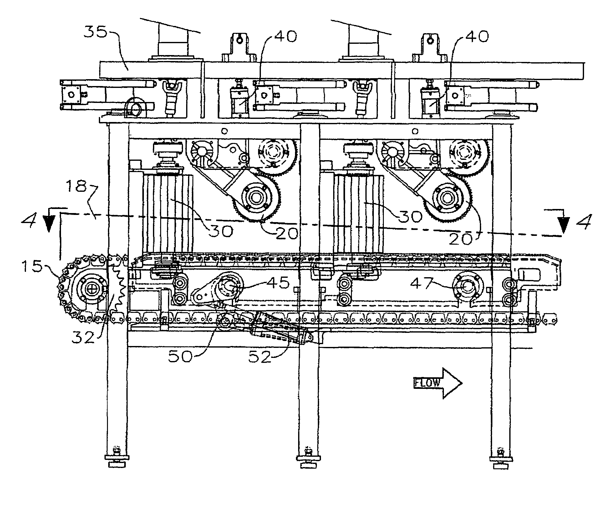
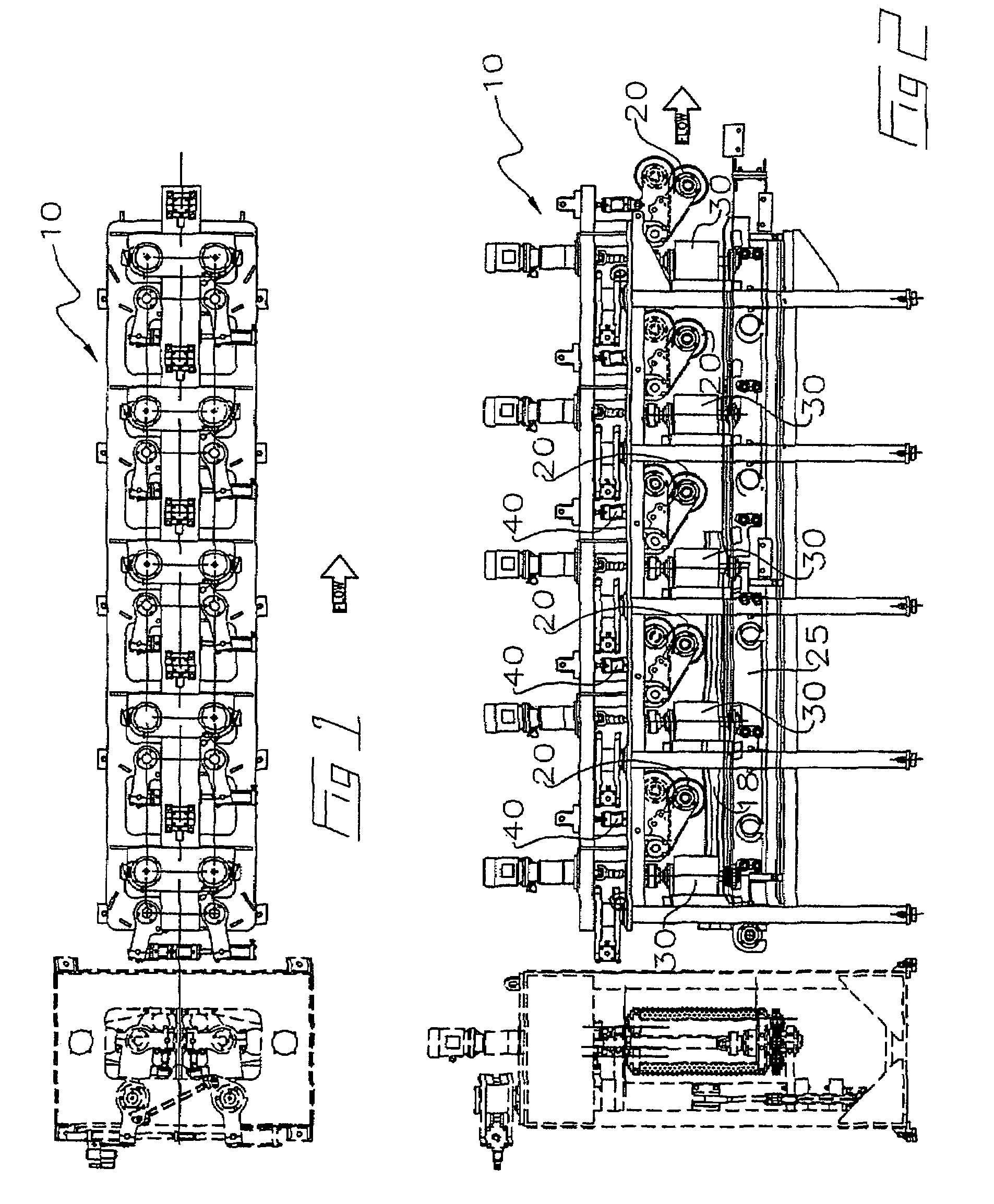
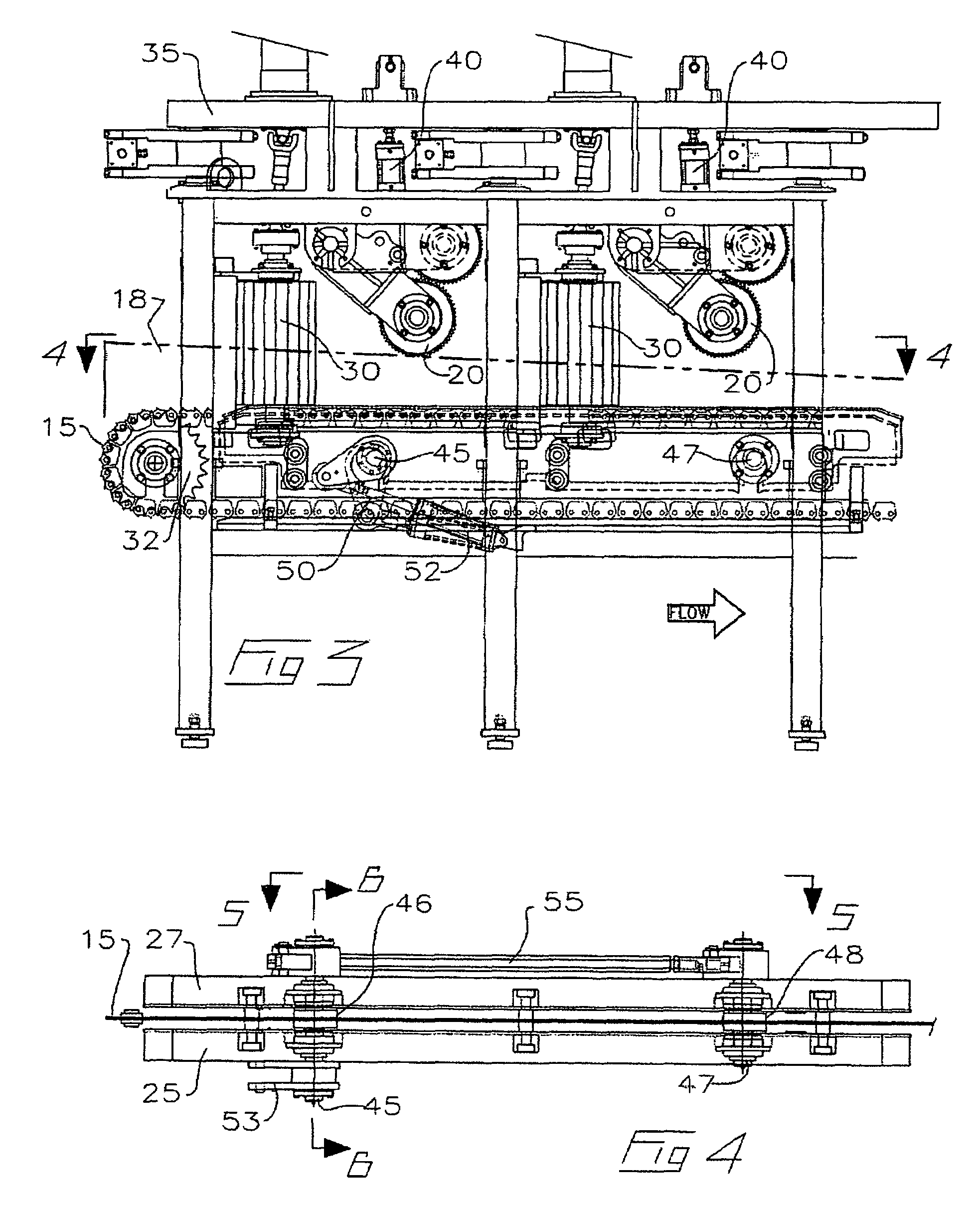
[0030]With reference to FIGS. 1 to 9, wherein similar characters of reference denote corresponding parts in each view, the sharp chain conveyor system 10 according to the present invention includes a conveyor such as sharp chain 15 which engages the surface of a workpiece 18. A first and a second skid 25 and 27 mounted to conveyor system 10 are configured to raise and lower workpiece 18 relative to sharp chain 15. A plurality of rotatable positioning drive rolls 30 mounted on a frame 35 rotates workpiece 18 into an optimized position.

[0031]Preferably, sharp chain 15 is a continuous steel chain. Teeth on sharp chain 15 enable sharp chain 15 to secure and engage workpiece 18 for transporting workpiece 18 along conveyor system 10 towards a primary breakdown machine, such as a headsaw (not shown). Sharp chain 15 may be mounted in one embodiment at one end on a drive sprocket 32, which is driven by suitable means known in the art to transport a workpiece 18 along conveyor system 10. The ...


PUM


Abstract

A continuous sharp chain conveyor system is disclosed wherein a workpiece may be elevated from the sharp chain conveyor while the workpiece is transported down the sharp chain conveyor such that the workpiece may be rotated to maintain the workpiece in an optimized position. The system includes a sharp chain which engages the workpiece, a first and a second skid positionable parallel alignment with the sharp chain to elevate and lower the workpiece relative to the sharp chain, and pairs of rotatable positioning drive rolls positionable along the sharp chain to rotate the workpiece when the workpiece is elevated. The system may also include a plurality of hold-down rolls to maintain the workpiece on the sharp chain by exerting downward pressure on the workpiece. The pairs of rotatable positioning drive rolls may cooperatively displace the workpiece laterally and / or independently angularly displace the workpiece relative to the longitudinal centreline of the sharp chain.

Description

CROSS REFERENCE TO RELATED APPLICATION[0001]This application claims priority from U.S. Provisional Patent Application No. 60 / 641,445 filed Jan. 6, 2005 entitled Conveyor System.FIELD OF THE INVENTION[0002]This invention relates to the field of devices for positioning a workpiece in a sawmill, and more particularly, it relates to a system for positioning a workpiece on a sharp chain conveyor system.BACKGROUND OF THE INVENTION[0003]A workpiece, such as a log or a cant, having a maximum of 30 inches in diameter is typically transported on a sharp chain conveyor system. This is also typically known as a “Single Length Infeed” (SLI) system. Such a sharp chain conveyor system includes a conveyor chain having sharp teeth which extend vertically upwards from the conveyor chain to firmly engage and secure onto the surface of the workpiece. A plurality of parallel spaced apart turning rolls are perpendicular to the direction of flow of the sharp chain conveyor. The turning rolls may be moved ...

Claims


Application Information

Patent Timeline
Patent Type & Authority Patents(United States)
IPC IPC(8): B65G29/00
CPCB27B31/006B27B31/003
Inventor MITCHELL, RORY M.
Owner USNRKOCKUMS CANCAR
Why Eureka
Try Eureka