Bipolar pulse generators with voltage multiplication

a technology of bipolar pulse generator and voltage multiplication, which is applied in the direction of pulse train generator, pulse manipulation, pulse technique, etc., can solve the problems of reducing the efficiency of impedance transformers. achieve the effect of small overall length, low cost and low cos

Active Publication Date: 2009-12-15
BAE SYST INFORMATION & ELECTRONICS SYST INTERGRATION INC
View PDF29 Cites 16 Cited by
  • Summary
  • Abstract
  • Description
  • Claims
  • Application Information

AI Technical Summary

Benefits of technology

[0011]According to still another embodiment of the present invention, the bipolar pulse generator may further include a stepped transmission line between the switch and the embedded transmission line segment that facilitates impedance transformation. The impedance of the stepped transmission line may increase for each successive step. Moreover, the load and the second transmission line structure may have impedances that are higher than the stepped transmformer. The bipolar pulse generator according to these embodiments may have a small overall length and high efficiency and may be useful in HPM generation, in particle accelerators and in other high voltage physical instruments and test equipment.

Problems solved by technology

This low range of characteristic impedances frequently causes problems when coupling high powered and high energy density transmission line pulse generators with radiating impedances.
Impedance transformers used to perform impedance transformations starting from low impedances may have especially low efficiency and large sizes.
Therefore, the transformers themselves can defeat some of the advantages of high powered and high energy density transmission line generators.
Moreover, problems presently exist with creating impedance transformers that increase impedance by large ratios.
Such a design is complicated.
However, Bipolar pulse generators with electrical energy storage in charged transmission lines conventionally have not provided enough impedance transformations based on charged stepped transmission lines.
Accordingly, for high efficiency of bipolar generation systems with conventional, for example exponential, transformers, the total size has conventionally been large and the designs complicated or impractical.

Method used


Image

  • Bipolar pulse generators with voltage multiplication
  • Bipolar pulse generators with voltage multiplication
  • Bipolar pulse generators with voltage multiplication

Examples


Embodiment Construction

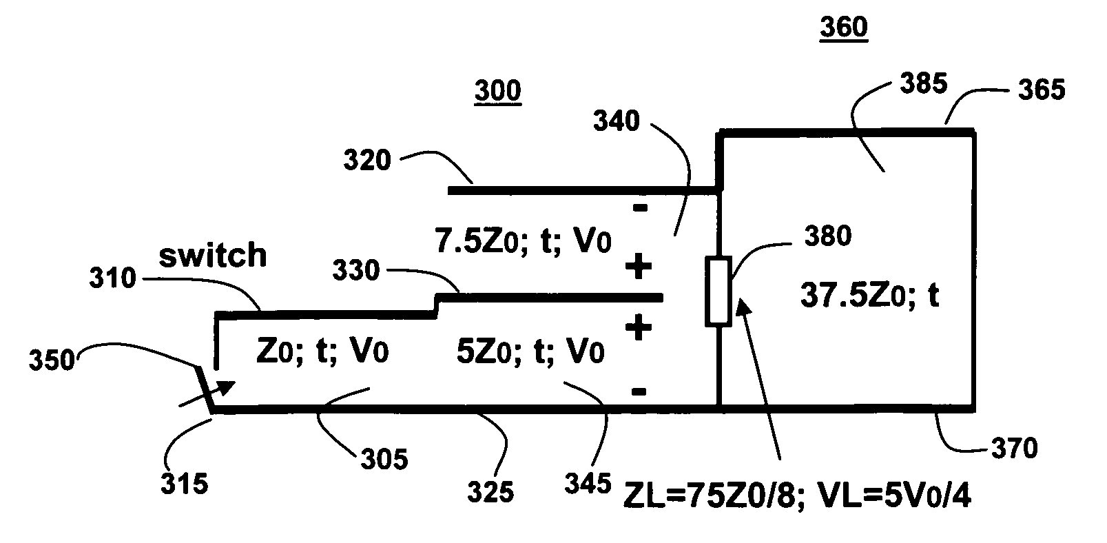
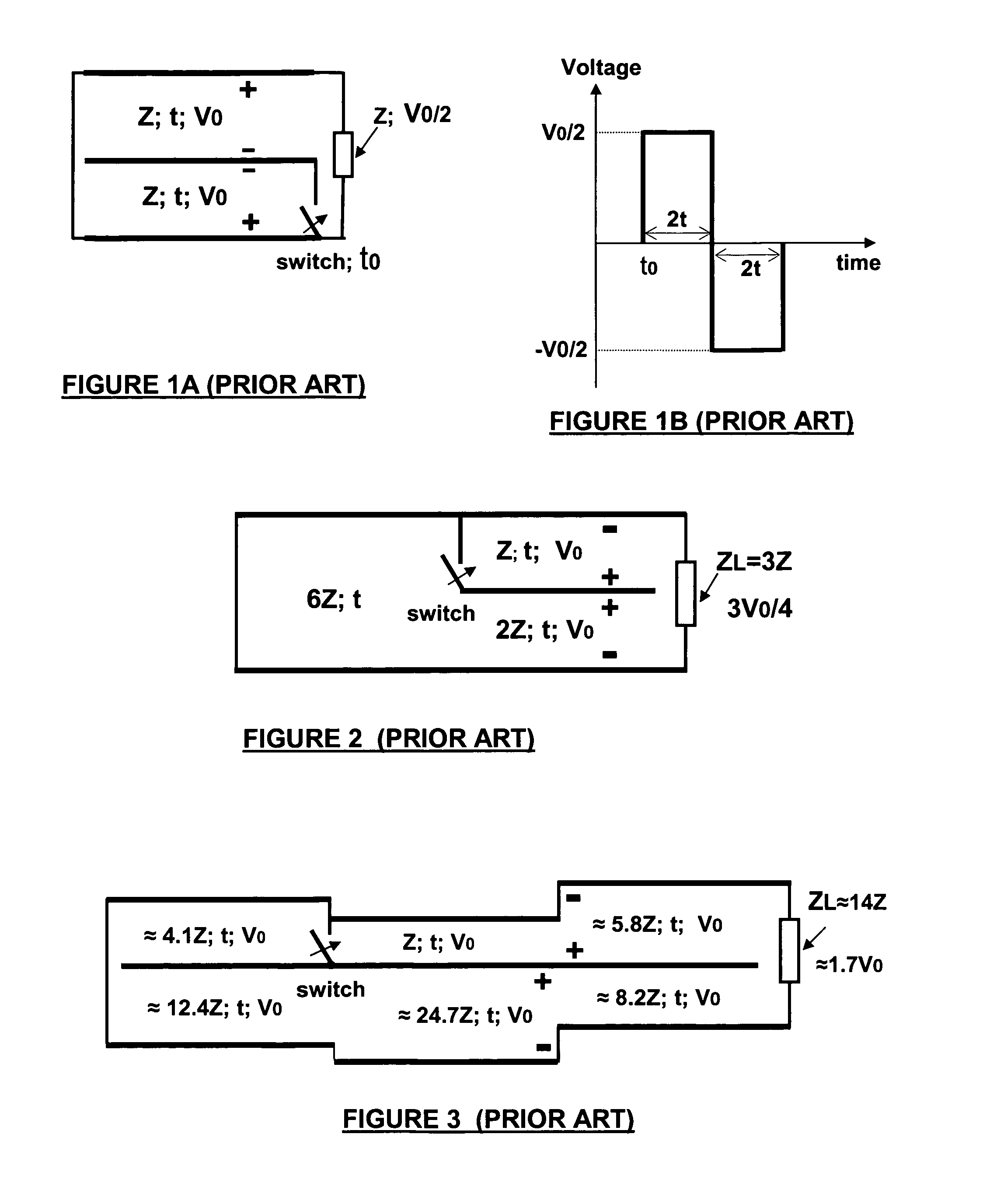
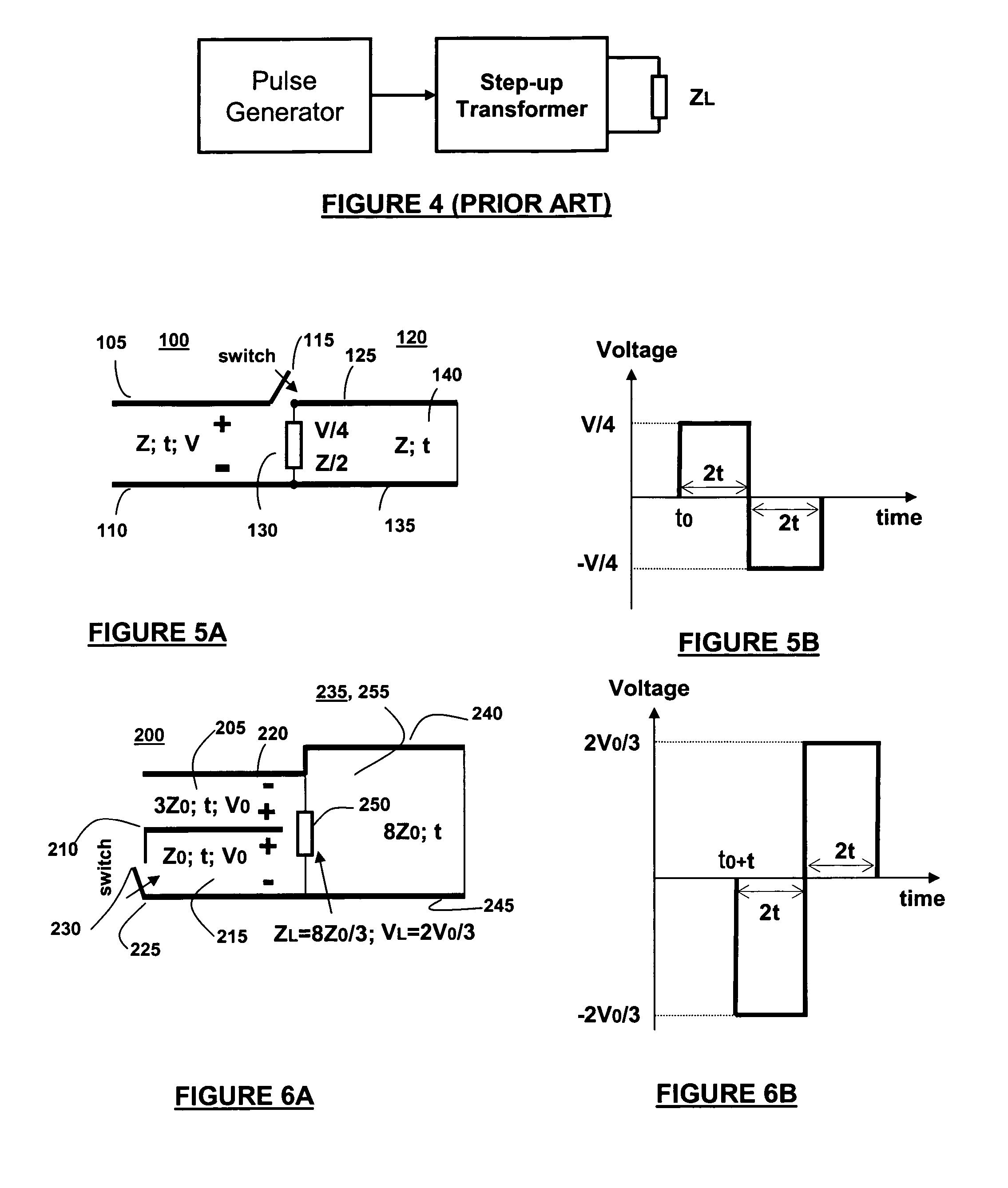
[0043]According to the present invention, a bipolar pulse generator includes two, two-conductor transmission lines coupled together with a load positioned between the two transmission lines. One transmission line is charged and is switchably coupled to the second transmission line to produce a bipolar pulse on a matched load. This bipolar pulse generator may be implemented in a flat or a folded design. Each conductor of the transmission line will be termed a segment. A transmission line includes at least two conductors, i.e. two segments.

[0044]In FIG. 5a, the simplest bipolar pulse generator circuit, according to an embodiment of the present invention is shown. Referring to FIG. 5a, two transmission line structures 100, which is a simple transmission line in this case, and 120, are coupled together through switch 115. The switch 115 couples the segment 105 of transmission line structure 100 to segment 125 of transmission line structure 120. In addition, load 130 couples segment 125 ...


PUM


Abstract

A bipolar pulse generator includes two, two-conductor transmission lines coupled together with a load positioned between the two transmission lines. Each conductor of a transmission line we define as a segment. Two segments of one transmission line are charged and switchably coupled to two segments of the other transmission line to produce a bipolar pulse on the matched load. This bipolar pulse generator may be implemented in a flat or a folded design. The generator may include two transmission line structures coupled together with a load positioned between each transmission line structures. The first transmission line structure may include a stepped transmission line and an embedded transmission line segment. A switch may be coupled between the embedded transmission line segment and another segment of the transmission line structure. During operation, the first transmission line structure may be charged to a potential with the switch in the open position and, when the switch is closed, the charge on the first transmission line structure together with the second transmission line structure generates a bipolar pulse on the matched load.

Description

FIELD OF THE INVENTION[0001]The present invention relates generally to bipolar pulse generators and, more particularly, bipolar pulse generators that incorporate voltage or current multiplication circuitry.BACKGROUND OF THE INVENTION[0002]Modern trends in High Power Microwave (HPM) sources for a variety of applications are directed to increasing radiated power and efficiency as well as to increasing energy density (energy per unit volume). Transmission line pulse generators with photoconductive switches could achieve some of the best results.[0003]High powered and high energy density transmission line pulse generators imply low and very low (mOhm range) characteristic impedances of transmission lines by using thin dielectrics. This low range of characteristic impedances frequently causes problems when coupling high powered and high energy density transmission line pulse generators with radiating impedances. In this scenario, the total value of impedance transformation may increase b...

Claims


Application Information

Patent Timeline
Patent Type & Authority Patents(United States)
IPC IPC(8): H03K3/42
CPCH03K3/53H03K5/065H04L25/0278H04B1/7174H03K5/159
Inventor LONDON, SIMON Y.
Owner BAE SYST INFORMATION & ELECTRONICS SYST INTERGRATION INC
Why Eureka
Try Eureka