Relay device and server, and port forward setting method

a relay device and server technology, applied in the field of relay devices and servers, can solve the problems of insufficient global ip addresses, troublesome manual setting, and insufficient in respect of the practical utilization of ports

Inactive Publication Date: 2009-12-15
PANASONIC CORP
View PDF20 Cites 24 Cited by
  • Summary
  • Abstract
  • Description
  • Claims
  • Application Information

AI Technical Summary

Benefits of technology

[0030]Alternatively, the assignment of the address of a DHCP can be properly performed. Also in the case in which a relay device for rewriting an IP address or a port number to transfer a packet is present between a client and a server, it is possible to dynamically generate a web page linked to the server such as a camera server and to give access from a client terminal to a router, thereby acquiring information from the server.

Problems solved by technology

However, the absolute number of global IP addresses (hereinafter referred to as external IP addresses) is insufficient in an existing IP protocol IPv4.
However, the manual setting is troublesome, and furthermore, is insufficient in respect of the practical utilization of a port.
After all, it is impossible to ensure a router to which access is given from the WAN side.
In case of a conventional UPnP standard compatible router connected in two stages, there is the drawback in routing.
In such relay devices, a user is to set an address range to be assigned to the terminal to be the follower by a manual operation, and a heavy burden is imposed on a user having no expertise.
However, there is a possibility that the first network and the set address range might be coincident or overlap with each other.
In the case in which there is no upper relay device for assigning an address range for a DHCP to the relay device, the problem cannot be solved.
As described above, in the case in which the addresses overlap with each other at the first network side and the second network side, there is a problem in that the routing of a packet between the networks cannot function well.
However, there is not considered a countermeasure to be taken against the case in which a relay device for rewriting an IP address or a port number to transfer a packet is present between a client and a server.

Method used


Image

  • Relay device and server, and port forward setting method
  • Relay device and server, and port forward setting method
  • Relay device and server, and port forward setting method

Examples


first embodiment

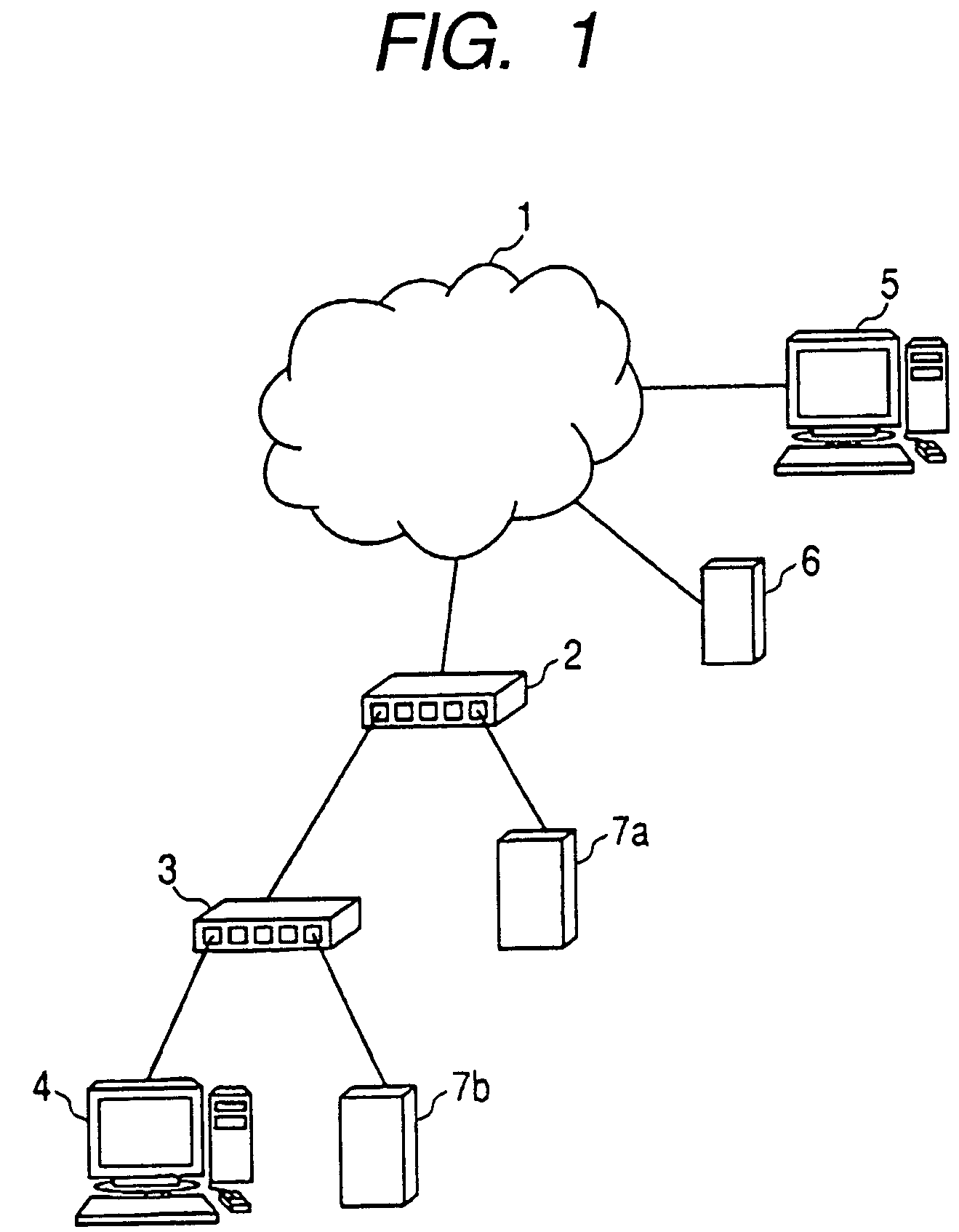
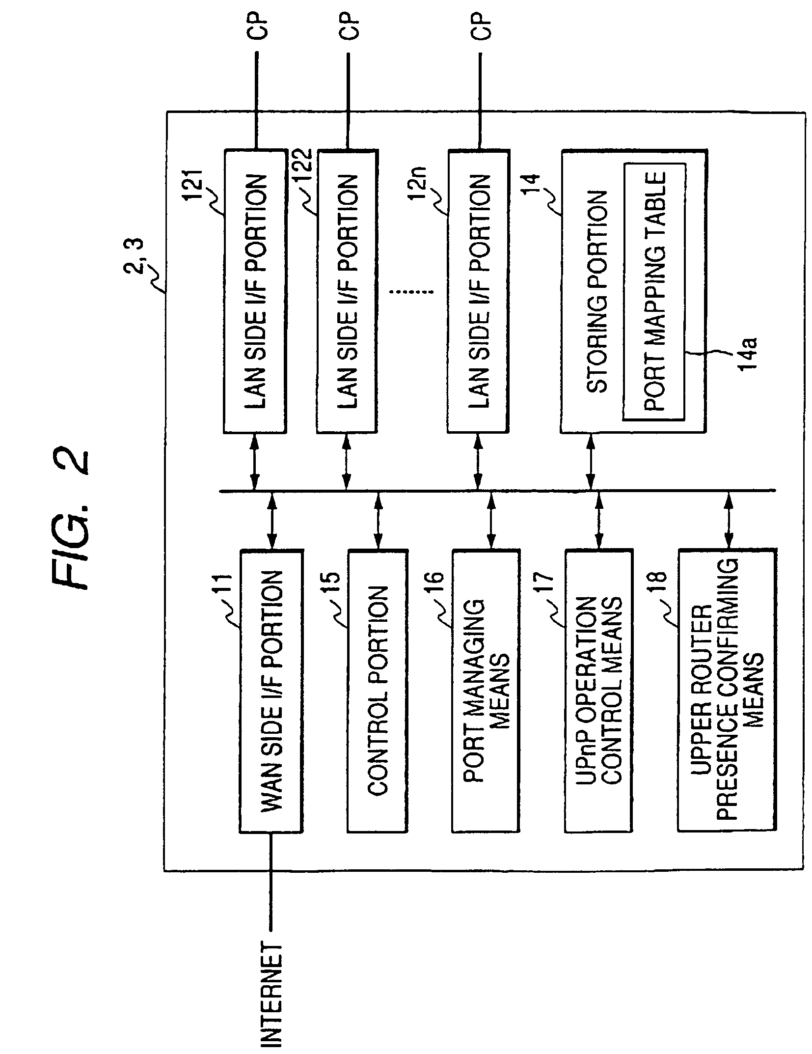
[0058]Description will be given to a relay device and a port forward setting method according to a first embodiment of the invention. FIG. 1 is an explanatory view showing a relay device (router) according to the first embodiment of the invention which is provided in two stages between an internet and a CP, FIG. 2 is a diagram showing the structure of the relay device according to the first embodiment of the invention, FIG. 3 is a flow chart showing a port assignment according to the first embodiment of the invention, FIG. 4 is a flow chart showing a procedure for setting the relay device according to the first embodiment of the invention, FIG. 5A is a first flow chart showing the confirmation of the presence of an upper relay device which is to be performed from the relay device according to the first embodiment of the invention, FIG. 5B is a second flow chart showing the confirmation of the presence of the upper relay device which is to be performed from the relay device according...

second embodiment

[0115]A second embodiment of the invention will be described below with reference to each drawing.

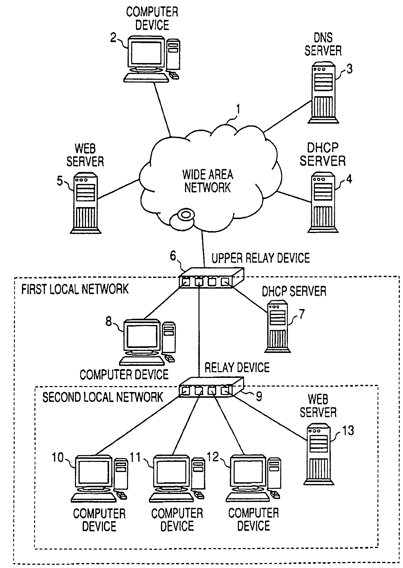
[0116]FIG. 9 is a view showing the structure of a network system including a relay device according to the second embodiment of the invention.

[0117]In FIG. 9, a reference numeral 1 denotes a wide area network such as an internet, and a reference numeral 2 denotes a computer device (hereinafter referred to as a PC) connected to the wide area network 1. The computer device 2 has general purpose browser means and can give access to a web server 5 which will be described below, thereby displaying a web page.

[0118]A reference numeral 3 denotes a DNS (Domain Name System) server which relates an IP address assigned to an apparatus connected to the wide area network 1 and a host name corresponding thereto and stores them, and retrieves the stored information when receiving a request for the IP address of an apparatus having a certain host name through the wide area network 1 from a client, and ...

third embodiment

[0160]While the address of the DHCP assignment address storing means 25a is changed by the address range setting means 26b when the address overlap detecting means 26a decides that the addresses overlap with each other in the second embodiment, the address range setting means 26b is not operated until a request is sent from the PC 10 to the relay device 9 even if the address overlap detecting means 26a decides that the addresses overlap with each other in a third embodiment of the invention. Specific description will be given.

[0161]Since the structure of a relay device according to the third embodiment of the invention is basically the same as that of FIG. 10 and only the operation of control means is different, description thereof will be omitted. 27 denotes a push type switch portion. When the switch portion is pushed, the address range setting means 26b is operated.

[0162]The operation of the relay device 9 will be specifically described by using a flow chart of FIG. 14. Reference...


PUM


Abstract

The present invention has an object to provide a relay device capable of performing dynamic port forward setting to open a port even if performing a connection in two stages and being connected to a network and a port forward setting method, and relates to a router for relaying a data packet which has such a structure as to comprise a control portion for giving a port forward setting request to an upper router 2 to perform the port forward setting of the upper router 2 and to relate port forward setting for a CP4 to port forward setting of a router upon receipt of the port forward setting request from the CP4 when a WAN side I / F portion is connected to an internet 1 through the upper router 2 and a LAN side I / F portion is connected to the CP4.

Description

BACKGROUND OF THE INVENTION[0001]1. Field of the Invention[0002]The present invention relates to a relay device and a server which relays a data packet, and particularly to a relay device capable of performing dynamic port forward setting and a setting method thereof.[0003]2. Description of the Related Art[0004]In order to always perform a connection to a wide area network such as an internet, the spread of a CATV has become serious and the spread of a broad band router has also become remarkable. However, the absolute number of global IP addresses (hereinafter referred to as external IP addresses) is insufficient in an existing IP protocol IPv4. For this reason, a countermeasure is taken against the shortage of the external IP address by using an NAT (Network Address Translation) function and a port forwarding function (a static IP masquerade).[0005]The NAT function serves to convert a local IP address (an internal IP address which will be hereinafter referred to as an IP address) ...

Claims


Application Information

Patent Timeline
Patent Type & Authority Patents(United States)
IPC IPC(8): H04L12/28G06F13/00H04L12/56H04L29/08H04L29/12
CPCH04L29/12283H04L29/12367H04L29/12924H04L67/02H04L61/2015H04L61/2061H04L61/2514H04L61/6063H04L49/3009H04L49/602H04L61/5061H04L2101/663H04L61/5014H04L61/50H04L61/00H04L61/25
Inventor YOKOMITSU, YASUSHIHIRAHARA, KAZUOKONISHI, HIROSHI
Owner PANASONIC CORP
Why Eureka
Try Eureka