Speaker and device using the same

a technology of loudspeaker and speaker, applied in the direction of loudspeaker diaphragm shape, transducer details, electrical transducers, etc., can solve the problems of unnecessary resonance and affect the characteristics of sound pressure frequency, and achieve the effects of high sound pressure level, small thickness, and high frequency rang

Active Publication Date: 2009-12-15
PANASONIC CORP
View PDF27 Cites 3 Cited by
  • Summary
  • Abstract
  • Description
  • Claims
  • Application Information

AI Technical Summary

Benefits of technology

[0013]This loudspeaker has a small thickness, has a high sound pressure level in a high frequency range, and secures a wide reproduction range in high frequencies.

Problems solved by technology

The diaphragm, having a reduced height H106, has a small rigidity, hence causing unnecessary resonance and affecting its sound pressure frequency characteristics.

Method used


Image

  • Speaker and device using the same
  • Speaker and device using the same
  • Speaker and device using the same

Examples


exemplary embodiment 1

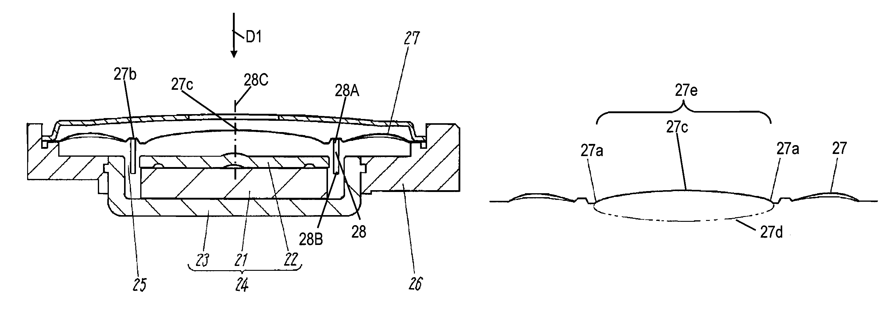
[0032]FIG. 1 is a cross-sectional view of a loudspeaker according to Exemplary Embodiment 1 of the present invention. Magnetic circuit 24 includes upper plate 22, yoke 23, and magnet 21 sandwiched between upper plate 22 and yoke 23, and has magnetic gap 25. Yoke 23 is coupled to frame 26. Cylindrical voice coil 28 has a circular shape as seen from direction D1. One end 28A of voice coil 28 is coupled to diaphragm 27 and the other end 28B is positioned in magnetic gap 25 of magnetic circuit 24.

[0033]FIG. 2 is a cross-sectional view of diaphragm 27 in a plane including center axis 28C of voice coil 28 of the loudspeaker shown in FIG. 1. In portion 27e of diaphragm 27 provided from coupling section 27b at which voice coil 28 is coupled with the diaphragm to center 27c, diaphragm 27 has a cross section having an elliptic arc of ellipse 27d (which, as shown, is a non-circular ellipse). Neighborhood 27a of coupling section 27b of diaphragm 27 has a small curvature to provide diaphragm 27 ...

exemplary embodiment 2

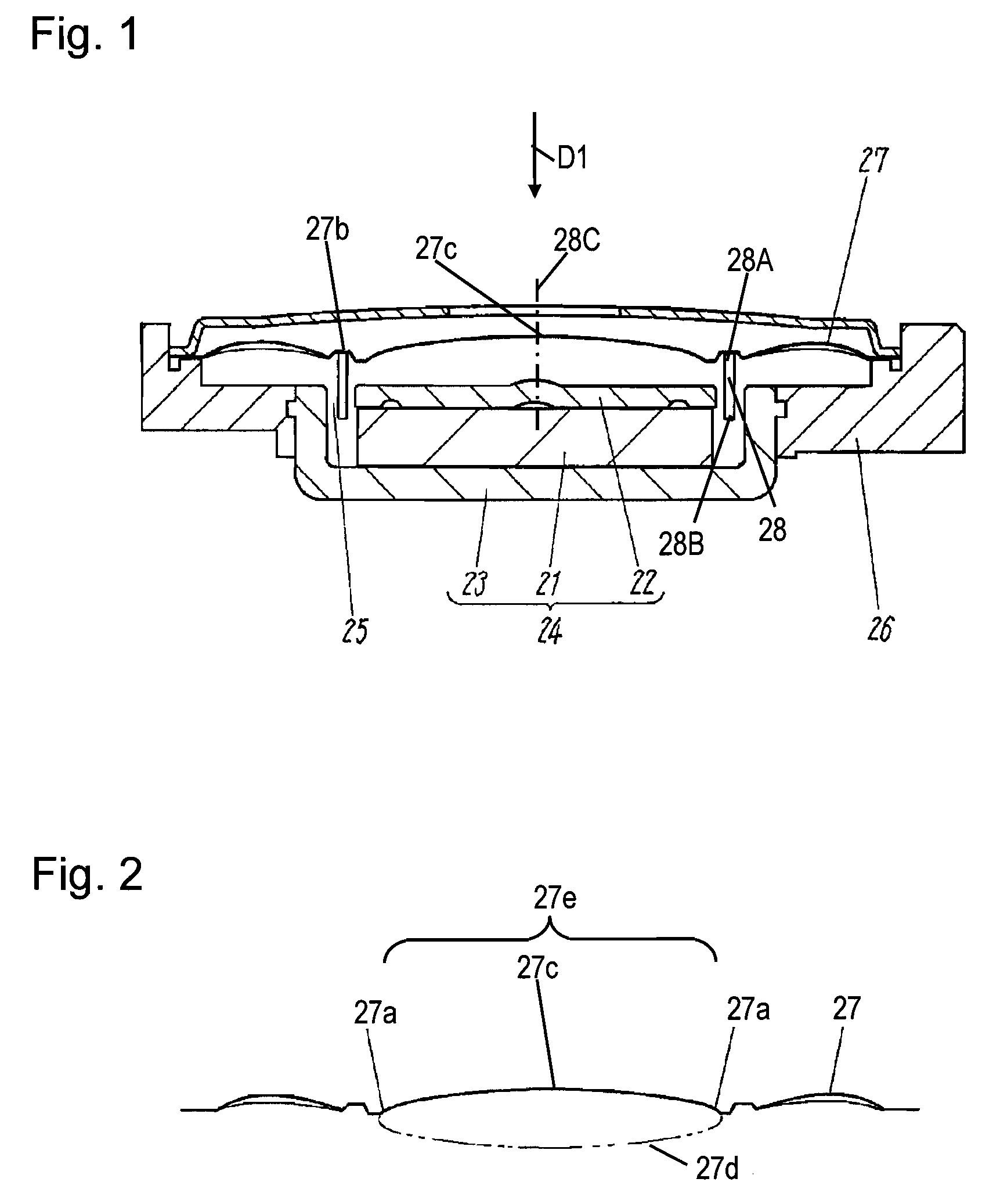
[0034]FIG. 3 is a cross-sectional view of diaphragm 29 of a loudspeaker according to Exemplary Embodiment 2 of the present invention. The loudspeaker shown in FIG. 3 has the same components as those of the loudspeaker according to Embodiment 1 shown in FIG. 1 except for the diaphragm, and their description is omitted.

[0035]Portion 29f of diaphragm 29 is provided from coupling section 29b at which voice coil 28 is coupled with the diaphragm to center 29c. Portion 29f has a cross section having a shape including respective arcs of two circles 29d and 29e having different radii and connected to each other. That is, portion 29f has the cross section including arc portion 29g of circle 29d and arc portion 29h of circle 29e. Portion 29g adjoins portion 29h and is farther from coupling section 29b than portion 29h. Circle 29e closer to coupling section 29b has a radius smaller than that of circle 29d closer to center 29c. This arrangement increases the rigidity in the neighborhood 29a of c...

exemplary embodiment 3

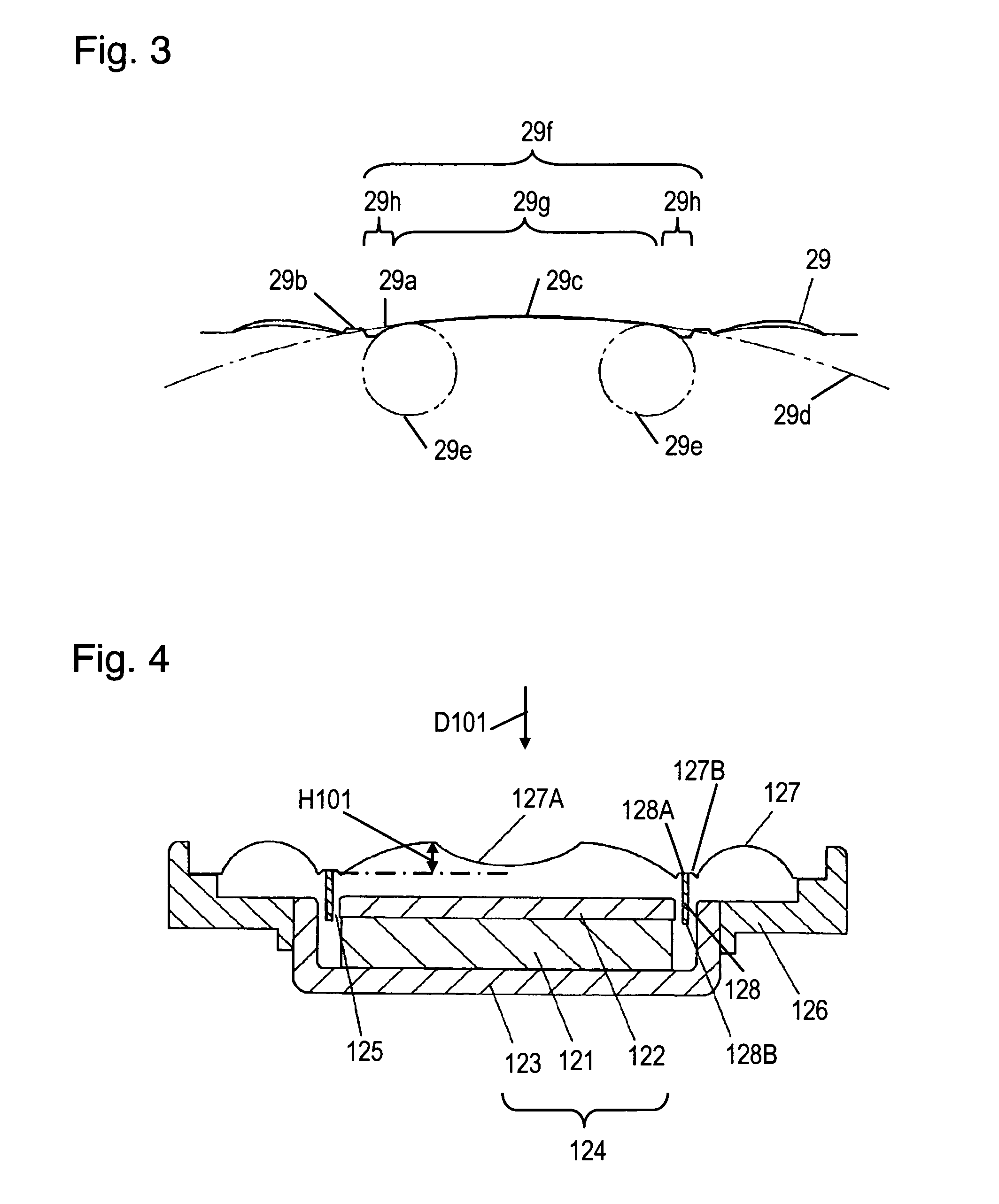
[0036]FIG. 4 is a cross-sectional view of a loudspeaker according to Exemplary Embodiment 3 of the present invention. FIG. 5 is a plan view of the loudspeaker shown in FIG. 4. Internal-magnet type magnetic circuit 124 includes upper plate 122, yoke 123, and magnet 121 sandwiched between upper plate 122 and yoke 123, and has magnetic gap 125. Yoke 123 is coupled with elliptical frame 126. Elliptical frame 126 has a non-circular shape. A periphery of elliptical frame 126 is adhered with the outer periphery of elliptical diaphragm 127 for covering the inner and outer sides of voice coil 128. Voice coil 128 has a cylindrical shape and a cross section having a circular shape seen from direction D101. One end 128A of voice coil 128 is coupled to diaphragm 127 at coupling section 127B while the other end 128B is positioned in magnetic gap 125 of magnetic circuit 124. The inner portion of diaphragm 127 inside coupling section 127B at which voice coil 128 is coupled to the diaphragm has dent...


PUM


Abstract

A loudspeaker includes a magnetic circuit having a magnetic gap, a frame coupled to the magnetic circuit, a voice coil having a first end positioned in the magnetic gap and a second end opposite to the first end, and a diaphragm coupled to the second end of the voice coil and the frame. The voice coil has a center axis provided through the first end and the second end. The diaphragm has a first portion in which the center axis of the voice coil is provided. The first portion of the diaphragm is provided inside the voice coil. The diaphragm further has a second portion outside the voice coil. One of the first portion and the second portion of the diaphragm has a cross section in a plane including the center axis, and the cross section of the one of the first portion and the second portion of the diaphragm has an elliptic-arc shape. This loudspeaker has a small thickness, has a high sound pressure level in a high frequency range, and secures a wide reproduction range in high frequencies.

Description

FIELD OF THE INVENTION[0001]The present invention relates to a loudspeaker and an apparatus using the loudspeaker, such as an acoustical device, an information communication device, a portable telephone, or a game device.BACKGROUND OF THE INVENTION[0002]A conventional loudspeaker disclosed in Japanese Utility Model Laid-Open Publication No. 59-50191 will be described. FIG. 16 is a cross-sectional view of the conventional loudspeaker. FIG. 17 is a cross-sectional view of a diaphragm, an essential portion of the conventional loudspeaker. Magnetic circuit 4 includes upper plate 2, yoke 3, and magnet 1 provided between upper plate 2 and yoke 3. Yoke 3 is coupled to frame 6 with an adhesive. A periphery of frame 6 is adhered to diaphragm 7. Voice coil 8 is adhered to diaphragm 7 and is positioned in magnetic gap 5 of magnetic circuit 4. As shown in FIG. 17, diaphragm 7 has convex portion 7a at the center portion. Convex portion 7a has an arc cross section.[0003]In order to have a small t...

Claims


Application Information

Patent Timeline
Patent Type & Authority Patents(United States)
IPC IPC(8): H04R25/00H04R7/14H04R9/04
CPCH04R9/045H04R7/14H04R2307/207H04R2499/13H04R2499/11H04R1/02H04R9/04
Inventor TAKASE, TOMOYASUENOMOTO, MITSUTAKAYAMASAKI, KAZUYAKUBO, KAZUTAKASHIMOKAWATOKO, TAKESHISUMIYAMA, MASAHIDE
Owner PANASONIC CORP
Why Eureka
Try Eureka