Ejector system for a vehicle and ejector system controller

a technology of ejector system and ejector, which is applied in the direction of electrical control, process and machine control, etc., can solve the problems of affecting the air-fuel ratio, and the increase of the operating load placed on the vehicle operator, so as to prevent the blockage of the ejector and the adverse influence of the air-fuel ratio, the effect of minimal additional cos

Inactive Publication Date: 2009-12-15
TOYOTA JIDOSHA KK
View PDF11 Cites 18 Cited by
  • Summary
  • Abstract
  • Description
  • Claims
  • Application Information

AI Technical Summary

Benefits of technology

[0010]The present invention relates to an ejector system and controller for a vehicle, that inhibits the blockage of the ejector and adverse influence on the air-fuel ratio even if there is a time when the ejector does not operate. The vehicle ejector system and controller may be incorporated at minimal additional cost.
[0011]According to a first aspect of the present invention an vehicle ejector system having an ejector that generates a negative pressure that is greater than the negative pressure to be applied from an air intake passage of the intake system, which provides communication between the atmosphere and each cylinder of the internal combustion engine, and that supplies the negative pressure to a brake booster, an operation state changing device that either causes the ejector to operate or stop, and a controller that controls the operation state changing device, wherein when fuel is not injected in a combustion cycle of the internal combustion engine, the controller controls the operation state changing device to operate the ejector. That is, in the present invention, when fuel is not injected in the combustion cycle of the internal combustion engine, which is regarded as no adverse effect on the air-fuel ratio, the ejector is operated. Thus, the ejector is not only operated according to its originally desired operation but also operated during other times. In accordance with this aspect, it is possible to increase the amount of time when the intake air flows through the ejector without adversely affecting the air-fuel ratio. Thus, it is possible to inhibit the blockage of the ejector even if there is a time when the ejector does not operate during operation of the internal combustion engine. According to the above-noted aspect, because there is only a change in the control, it is possible to inhibit the blockage of the ejector with a low cost.
[0012]In a second aspect of the present invention, the operation state changing device may be controlled to operate the ejector when a fuel cut control of the internal combustion engine is executed. If the ejector is operated when the fuel cut control is executed as in the above-noted aspect, it is possible to increase the amount of time when the intake air flows through the ejector.
[0013]In a third aspect of the present invention, the operation state changing device may be controlled to operate the ejector when the ignition switch is off and the internal combustion engine is rotating. That is, even after the ignition switch is set to off, because the internal combustion engine rotates for some time until it completely stops, it is possible, for example as in the above-noted aspect, to have intake air flow through the ejector. According to the above-noted aspect, it is possible after the internal combustion engine stops to inhibit the blockage of the ejector that can occur resulting from the freezing of condensed water accumulated in the narrowed passage, and to inhibit deposits generated and fixed on the walls of the passage to aggravate the blockage of the ejector.
[0014]In a fourth aspect of the present invention, when the internal combustion engine is mounted in a hybrid vehicle that uses an electric motor as well as the internal combustion engine as a drive power source, and the operation state changing device may be controlled to operate the ejector when the drive power source is switched from the internal combustion engine to the electric motor. For example, in a so-called hybrid vehicle as well, using the above-noted aspect it is possible to inhibit the blockage of the ejector.
[0016]According to this aspect, it is possible to provide a low-cost ejector system and a controller that inhibit the blockage of the ejector and adverse affect on the air-fuel ratio even if there is a time when the ejector is not operated.

Problems solved by technology

In the vehicle controller, because the amount of intake air changes when the ejector operates, it is not possible to maintain a proper air-fuel ratio when idling.
In this case, because the brake booster is applying negative pressure from the intake system of the internal combustion engine, the brake assist function becomes insufficient, resulting in an increase in the operating load placed on the vehicle operator.
However, if the ejector is caused to function in this case, the air-fuel ratio is affected.
This makes it difficult to control the target idling rpm speed, which could result in unstable idling.
Although the simplest solution for this is to not cause the ejector to function, this results in the following problems.
If the ejector is not operated for a long period of time, because the intake air does not pass through the ejector, the passage tends to become blocked.
For this reason, in order to retrofit this negative pressure generating apparatus to a vehicle that has an ejector, it would be necessary not only to change the control, but also to replace the negative pressure generating apparatus and the already installed ejector, and change the control wiring and the controller, resulting in a great increase in cost.

Method used


Image

  • Ejector system for a vehicle and ejector system controller
  • Ejector system for a vehicle and ejector system controller
  • Ejector system for a vehicle and ejector system controller

Examples


Embodiment Construction

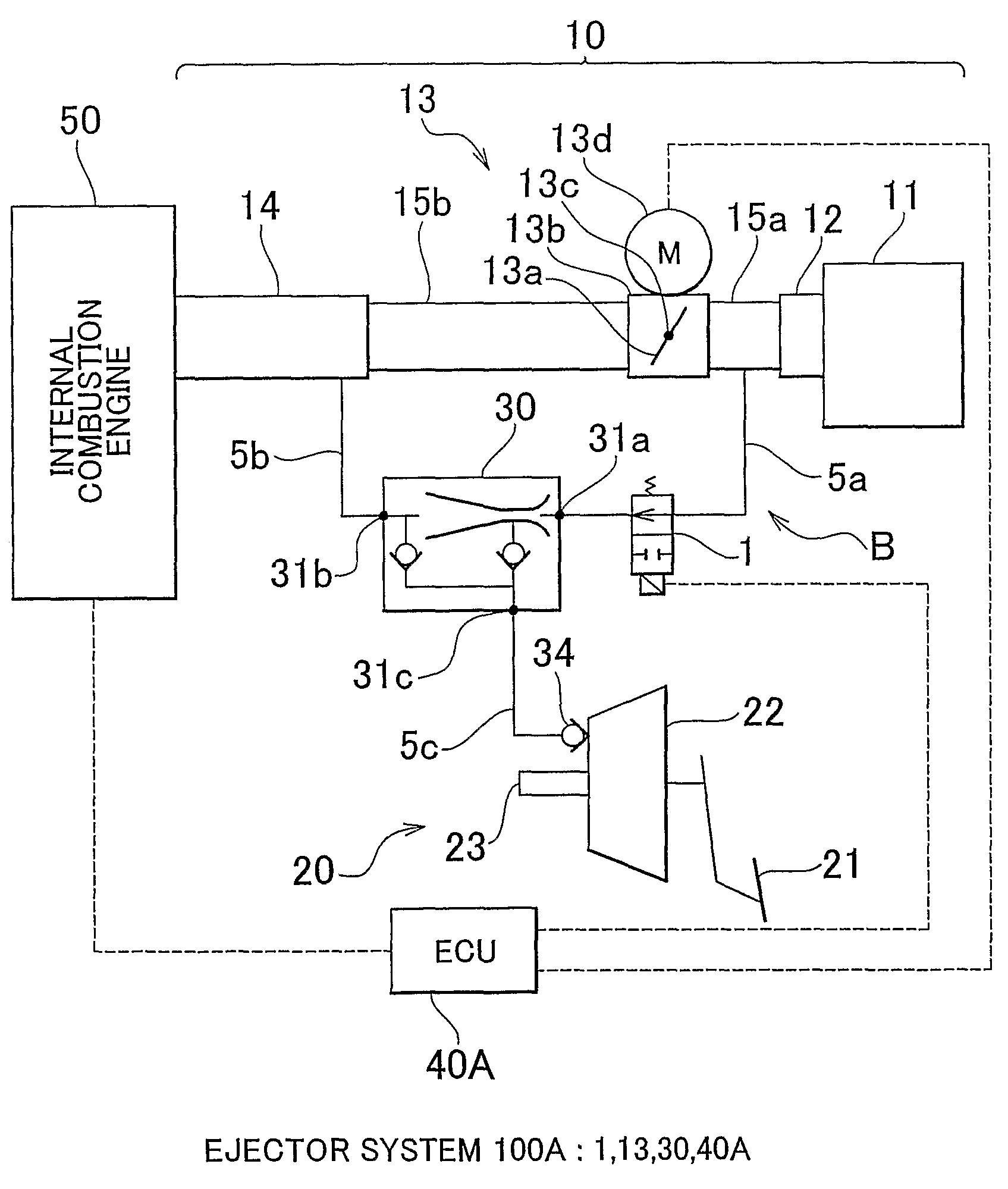
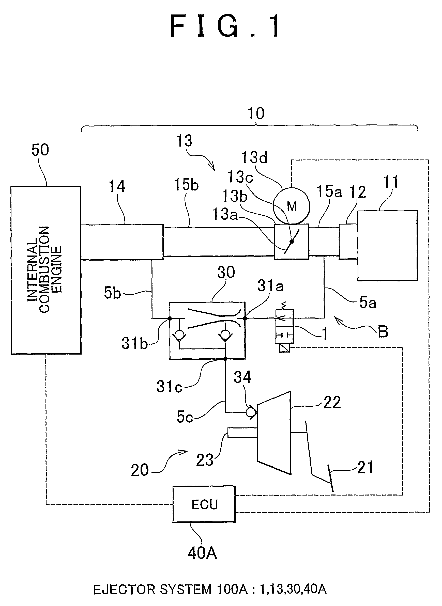
[0023]FIG. 1 is a schematic view of an ejector system 100A for a vehicle (hereinafter referred to simply as an ejector system) according to a first embodiment of the present invention. The constitutional elements shown in FIG. 1, including an internal combustion engine 50, are mounted in a vehicle (not illustrated). The air intake system 10 of the internal combustion engine 50 has an air cleaner 11, an air flow meter 12, an electric throttle 13, an intake manifold 14, intake ports (not illustrated) that communicate with cylinders (not illustrated) of the internal combustion engine 50, and air intake pipes 15a, 15b, for example, which are appropriately provided between these elements. The air cleaner 11 is configured to filter intake air supplied to each cylinder of the internal combustion engine 50, and is connected via an air duct (not illustrated) to the atmosphere. The air flow meter 12 is configured to measure the amount of intake air flow, and outputs a signal according to the ...


PUM


Abstract

A vehicle ejector system (100A) has an in-flow port (31a) and an out-flow port (31b) connected in the intake passage of an intake system (10) of an internal combustion engine (50), which provides communication between the atmosphere and each cylinder of the internal combustion engine, so as to include a throttle valve (13a) between the in-flow port (31a) and the out-flow port (31b). The ejector system (100A) also includes an ejector (30) that supplies negative pressure generated by the intake air passing between in-flow port (31a) and the out-flow port (31b) to a brake booster (22), a VSV (1) that allows the ejector (30) to operate and stop, and an ECU (40A) that controls the VSV (1), wherein in the combustion cycle of the internal combustion engine (50) the ECU (40A) controls the VSV (1) to operate the ejector (30).

Description

BACKGROUND OF THE INVENTION[0001]1. Field of the Invention[0002]The present invention relates to an ejector system for a vehicle and an ejector system controller, and more particularly to an ejector system for a vehicle having an ejector supplying a negative pressure to brake booster and an ejector system controller.[0003]2. Description of the Related Art[0004]In a conventional vehicle, in order to supply a brake booster with negative pressure that is greater than the negative pressure that is to be applied from an intake passage of the intake system, which provides communication between the atmosphere and each cylinder of an internal combustion engine, an ejector was used. The following vehicle controller has been described with regard to this ejector, for example in Japanese Patent Application Publication No. JP-A-2005-69175. In the vehicle controller, because the amount of intake air changes when the ejector operates, it is not possible to maintain a proper air-fuel ratio when id...

Claims


Application Information

Patent Timeline
Patent Type & Authority Patents(United States)
IPC IPC(8): F02D45/00B60T17/00B60W10/06B60W10/18B60W20/00F02D29/02F02D41/04F02D41/12
CPCB60K6/48B60T13/52B60T17/02F02D41/123B60W10/30Y02T10/6221B60W20/00Y02T10/62F02D41/04F02D29/02F02D45/00B60T17/00B60W20/15B60W2710/18B60W10/18B60W2510/06
Inventor HIROOKA, SHIGEMASA
Owner TOYOTA JIDOSHA KK
Why Eureka
Try Eureka