Waveform input circuit, waveform observation unit and semiconductor test apparatus

a technology of waveform observation and input circuit, which is applied in the direction of instruments, measurement using ac-dc conversion, and measurement using dc-ac conversion, etc. it can solve the problems of increasing the design cost of the test board, the rising edge of the device output waveform becomes dull, and the device output waveform cannot be faithfully observed by the conventional waveform observation unit, etc., to achieve the effect of reducing the capacity, suppressing the dullness of the device output waveform

Inactive Publication Date: 2009-12-15
ADVANTEST CORP
View PDF8 Cites 3 Cited by
  • Summary
  • Abstract
  • Description
  • Claims
  • Application Information

AI Technical Summary

Benefits of technology

[0026]The present invention has been made in view of the problems described above, and is directed to provide a waveform input circuit, a waveform observation unit and a semiconductor test apparatus which enable faithful observation of an output waveform of a device under test without adding a load driving circuit immediately after the device under test when observing the output waveform of the device under test which is not capable of driving a transmission line because of high output impedance and low load driving capability.

Problems solved by technology

However, some devices under test can not drive the transmission line because of high output impedance and low load driving capability, so that there has been a problem that an output waveform from the device under test can not be faithfully observed by the conventional waveform observation unit in some cases.
However, the following problems have occurred in the above solving means.
Thus, a problem arises wherein the rising edge of the device output waveform becomes dull (the rising edge delays) since the output waveform has to charge the capacitance including the transmission line.
Furthermore, the configuration shown in FIG. 10 is not desirable in that if circuits are added in the vicinity of the device under test 200, a design cost for the test board is increased, and problems are caused in reliability and maintainability.

Method used


Image

  • Waveform input circuit, waveform observation unit and semiconductor test apparatus
  • Waveform input circuit, waveform observation unit and semiconductor test apparatus
  • Waveform input circuit, waveform observation unit and semiconductor test apparatus

Examples


first embodiment

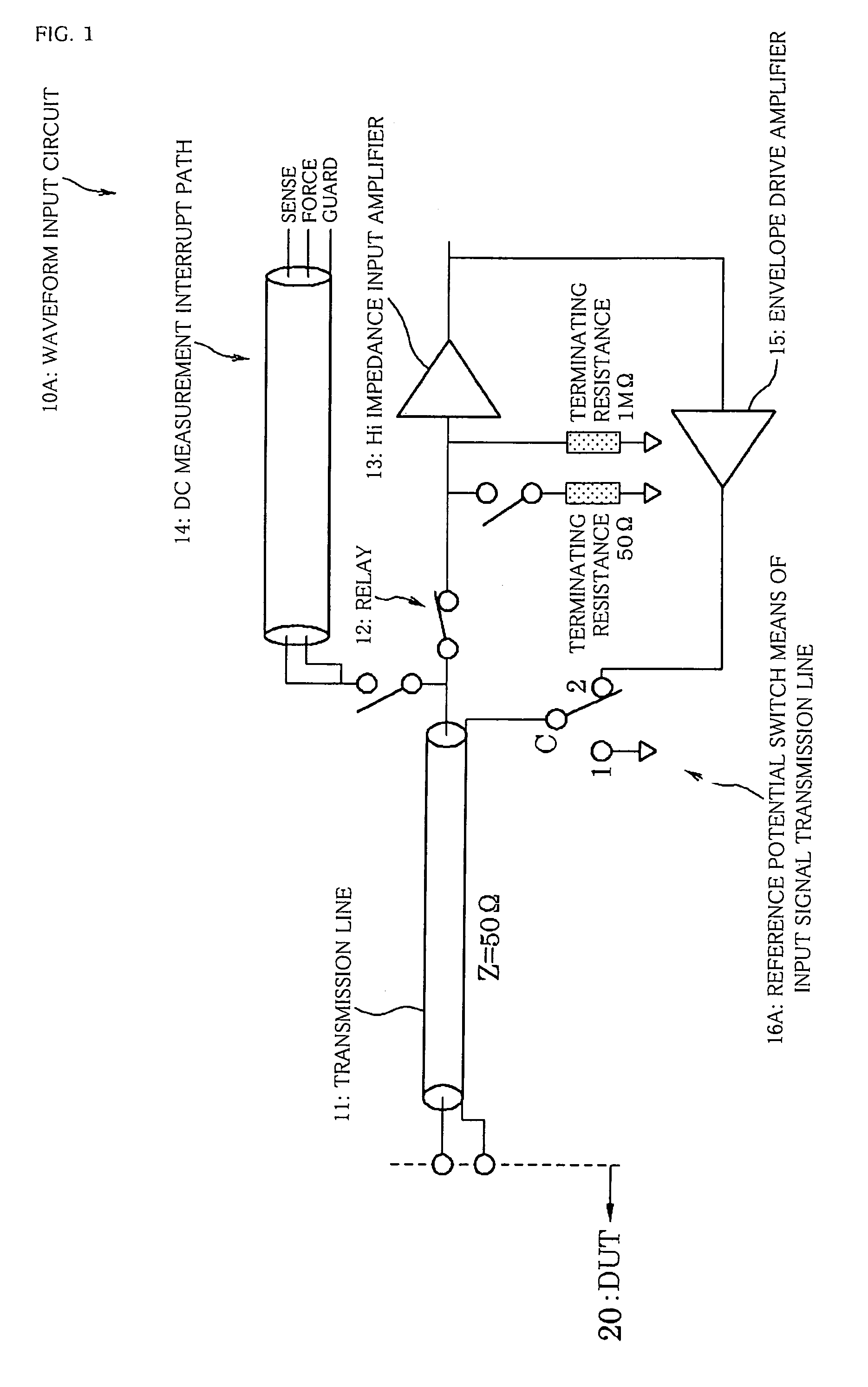
[0054]A first embodiment of a waveform input circuit of the present invention will first be described referring to FIG. 1.

[0055]FIG. 1 is a circuit configuration diagram showing the configuration of the waveform input circuit in the present embodiment.

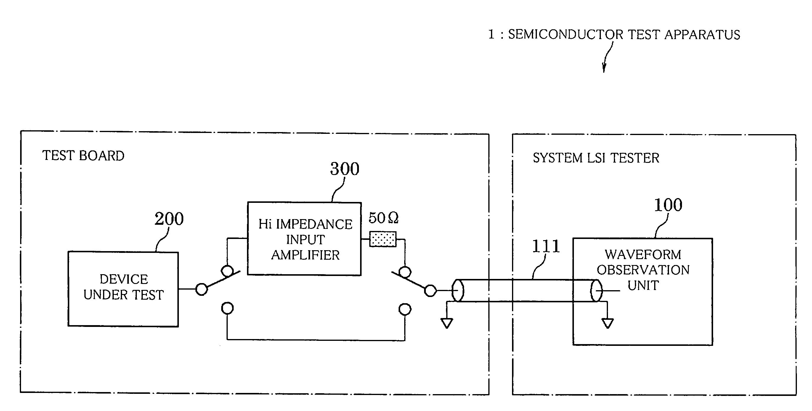
[0056]It is to be noted that the waveform input circuit in the present embodiment is a circuit provided as an input section of a waveform observation unit. Further, the waveform observation unit is a test unit provided in a semiconductor test apparatus to observe an analog output waveform of a device under test.

[0057]As shown in FIG. 1, a waveform input circuit 10a comprises a transmission line (input signal transmission line) 11 on which an output waveform from a device under test (DUT) 20 is transmitted, a terminating resistance 50Ω, a terminating resistance 1 MΩ (Hi impedance), a relay (selection means) 12 which selects any one of the terminating resistances, a Hi impedance input amplifier (input buffer) 13, and a DC measurement int...

second embodiment

[0069]Next, a second embodiment of a waveform input circuit of the present invention will be described with reference to FIGS. 5 and 6.

[0070]FIG. 5 shows the configuration of a conventional waveform input circuit comprising a plurality of transmission lines, and FIG. 6 shows the configuration of the waveform input circuit in the present embodiment.

[0071]The present embodiment is different from the first embodiment in that when a plurality of transmission lines is provided, the reference potential of one or two or more of the plurality of transmission lines can be switched by reference potential switch means of the input signal transmission lines. Other components are similar to those in the first embodiment.

[0072]Therefore, in FIG. 6, the same signs are assigned to the components similar to those in FIG. 1, and they will not be described in detail.

[0073]As shown in FIG. 5, a conventional waveform input circuit 110c has a configuration in which there is provided a plurality of transm...

third embodiment

[0082]Next, a third embodiment of a waveform input circuit of the present invention will be described with reference to FIG. 7.

[0083]FIG. 7 is a circuit configuration diagram showing the configuration of the waveform input circuit in the present embodiment.

[0084]The present embodiment is different from the first embodiment in that reference potential switch means of the input signal transmission line can select a guard potential which is a potential at a guard line of a DC measurement interrupt path. Other components are similar to those in the first embodiment.

[0085]Therefore, in FIG. 7, the same signs are assigned to the components similar to those in FIG. 1, and they will not be described in detail.

[0086]As shown in FIG. 7, a waveform input circuit 10c; of the present embodiment comprises a transmission line 11, a terminating resistance 50Ω, a terminating resistance 1 MΩ, a relay 12, a Hi impedance input amplifier 13 and a DC measurement interrupt path 14, as well as an envelope ...


PUM


Abstract

A waveform input circuit, waveform observation unit and semiconductor test apparatus allow to faithfully observe waveform of a device under test with high output impedance and low load driving capability. A waveform input circuit includes a high input impedance terminating resistance which receives an input signal from a transmission line, a relay which selects a terminating resistance, an input buffer which is connected when the high input impedance terminating resistance is selected. A reference potential switch is further provided to select a reference potential of the transmission line where one reference potential is controlled to be in phase with the input signal by an input buffer which is connected when the high input impedance terminating resistance is selected.

Description

BACKGROUND OF THE INVENTION[0001]1. Field of the Invention[0002]The present invention relates to a waveform observation unit capable of observing an analog waveform output from a device under test, a waveform input circuit corresponding to an input section of the waveform observation unit, and a semiconductor test apparatus comprising the waveform observation unit. More particularly, it relates to a waveform input circuit, a waveform observation unit and a semiconductor test apparatus suitable for enabling faithful observation of an output waveform of even a device under test which is not capable of driving a transmission line because of high output impedance and low load driving capability.[0003]2. Description of the Related Art[0004]Some semiconductor test apparatuses for which a device under test (DUT) is a semiconductor integrated circuit such as an IC or LSI comprise a waveform observation unit to observe an analog waveform output from the device under test (e.g., refer to Japa...

Claims


Application Information

Patent Timeline
Patent Type & Authority Patents(United States)
IPC IPC(8): G01R31/02
CPCG01R31/31926G01R31/31924
Inventor KAWABATA, MASAYUKI
Owner ADVANTEST CORP
Why Eureka
Try Eureka