Point-to-point ethernet hardware co-simulation interface

a hardware cosimulation interface and point-to-point ethernet technology, applied in software simulation/interpretation/emulation, instruments, program control, etc., can solve the problems of large overhead of fully capable ip/ethernet interfaces, degrade the speed of cosimulation, and require a large amount of hardware resources, so as to facilitate data transfer, facilitate communication, and facilitate data transfer

Active Publication Date: 2009-12-22
XILINX INC
View PDF6 Cites 18 Cited by
  • Summary
  • Abstract
  • Description
  • Claims
  • Application Information

AI Technical Summary

Benefits of technology

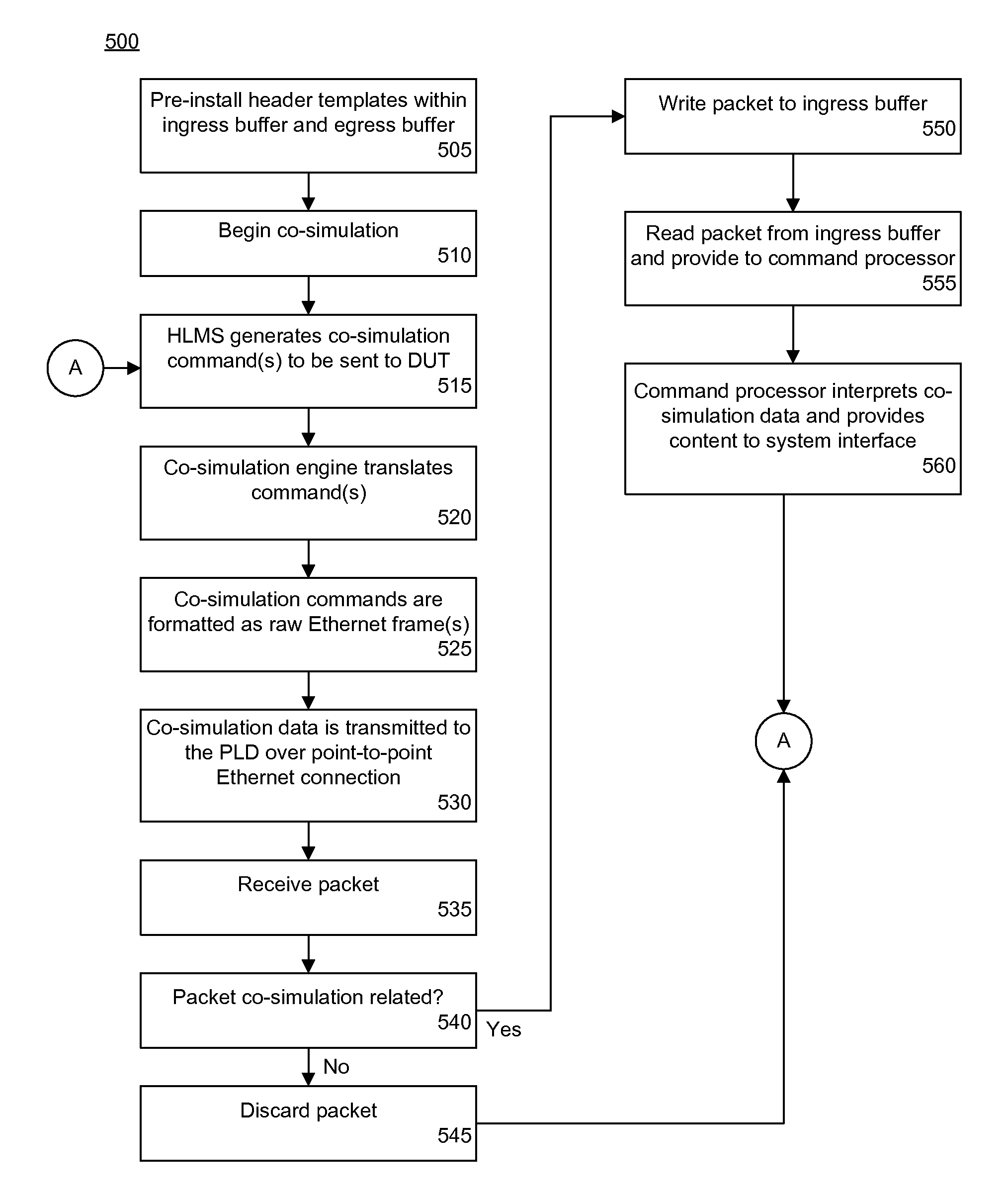
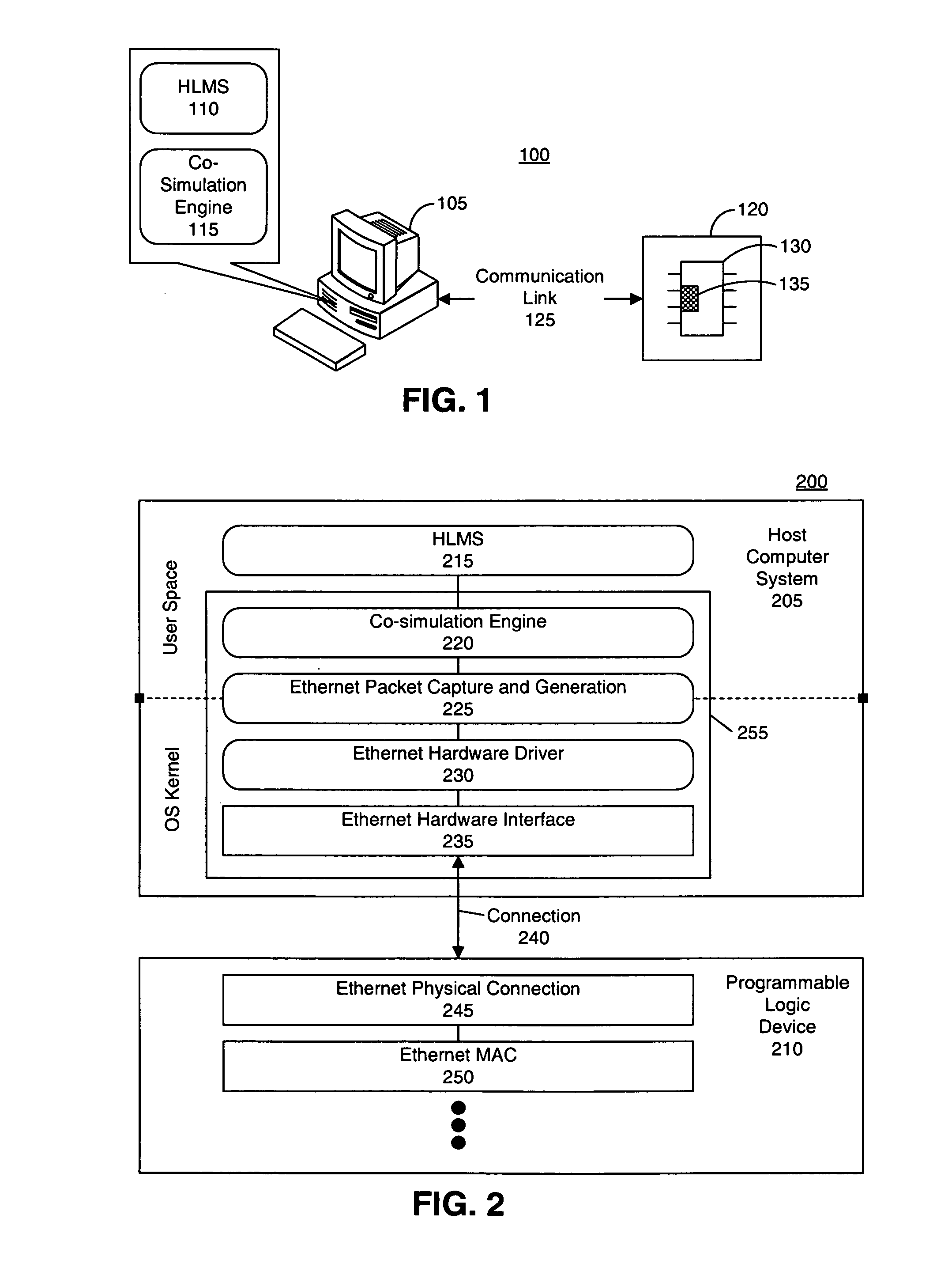
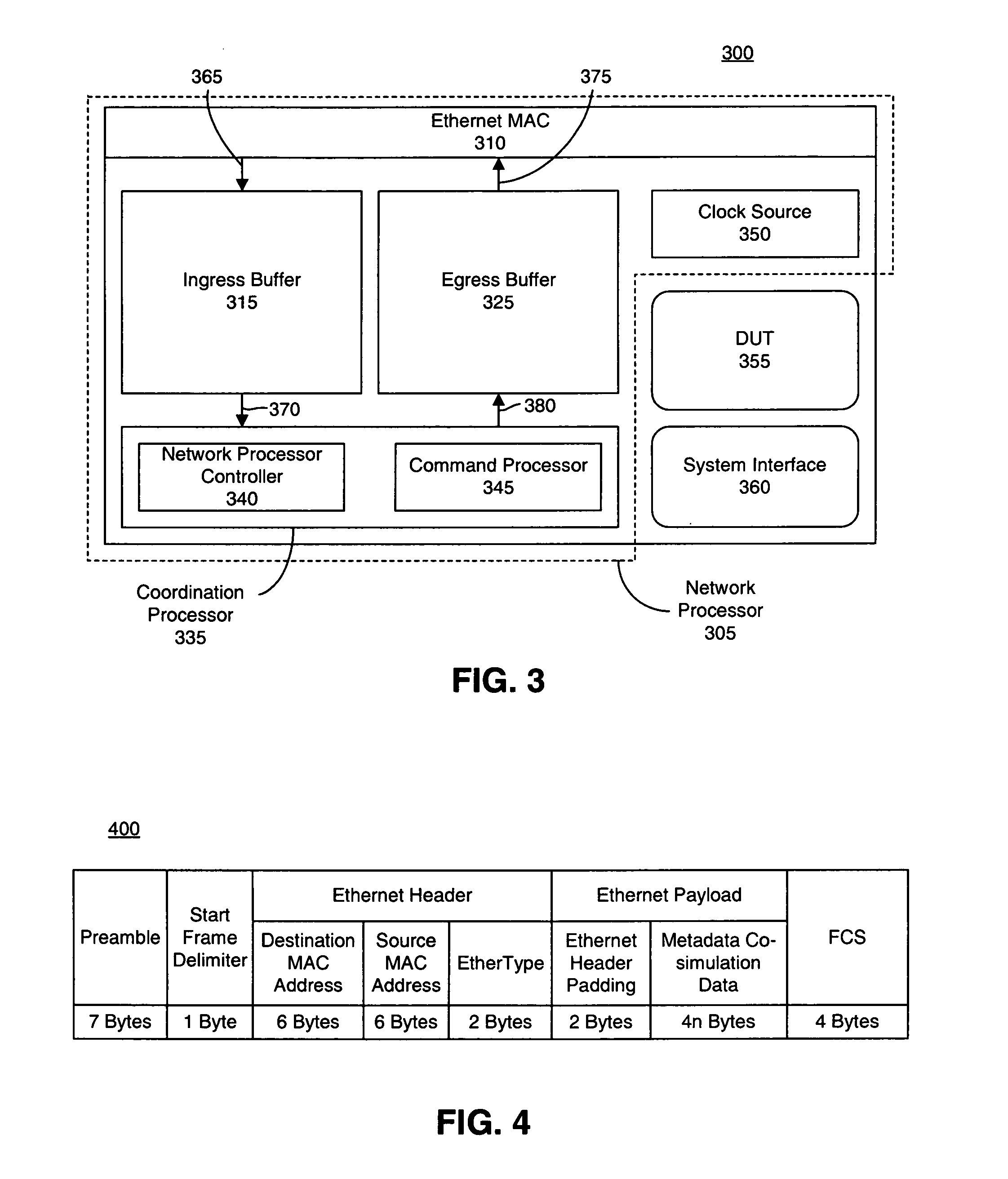
[0011]The present invention provides a software and hardware architecture for a hardware co-simulation interface and method of using the same. The embodiments disclosed herein facilitate communication between a host computing system and a device under test (DUT) that is implemented on a programmable logic device (PLD). One embodiment of the present invention can include an Ethernet co-simulation interface for use with a software-based simulation tool and a DUT disposed on a PLD. The co-simulation interface can include a host interface executing on a host computing system. The host interface facilitates data transfer between the software-based simulation tool and a communication link to the DUT. The co-simulation interface also can include a network processor implemented within the PLD. The network processor facilitates data transfer between the communication link and the DUT. The host interface and the network processor further can exchange simulation data formatted as Ethernet frames over a point-to-point Ethernet connection.

Problems solved by technology

While an IP / Ethernet-based interface does provide significant flexibility, a fully capable IP / Ethernet interface carries a large amount of overhead.
When an IP / Ethernet connection is used for co-simulation, functions such as address resolution, translation and routing, system configuration, collisions, and congestion can degrade the speed of co-simulation.
Additionally, implementing a protocol stack on a PLD, such as an FPGA, can be costly in terms of the hardware resources that are required.
Another challenge of a fully capable IP / Ethernet co-simulation implementation on a PLD is that it is difficult to maintain the speed of “in-fabric” packet processing at the same level as the speed of the IP / Ethernet connection itself.

Method used


Image

  • Point-to-point ethernet hardware co-simulation interface
  • Point-to-point ethernet hardware co-simulation interface
  • Point-to-point ethernet hardware co-simulation interface

Examples


Embodiment Construction

[0026]While the specification concludes with claims defining the features of the invention that are regarded as novel, it is believed that the invention will be better understood from a consideration of the description in conjunction with the drawings. As required, detailed embodiments of the present invention are disclosed herein; however, it is to be understood that the disclosed embodiments are merely exemplary of the invention, which can be embodied in various forms. Therefore, specific structural and functional details disclosed herein are not to be interpreted as limiting, but merely as a basis for the claims and as a representative basis for teaching one skilled in the art to variously employ the inventive arrangements in virtually any appropriately detailed structure. Further, the terms and phrases used herein are not intended to be limiting but rather to provide an understandable description of the invention.

[0027]The present invention provides a solution for a hardware co-...


PUM


Abstract

An Ethernet co-simulation interface for use with a software-based simulation tool and a design under test disposed on a programmable device can include a host interface and a network processor. The host interface can execute on a host computing system and facilitate data transfer between the software-based simulation tool and a communication link to the design under test. The network processor can be implemented within the programmable device and facilitate data transfer between the communication link and the design under test. The host interface and the network processor can exchange simulation data formatted as raw Ethernet frames over a point-to-point Ethernet connection.

Description

BACKGROUND[0001]1. Field of the Invention[0002]The present invention relates to the field of electronic system design and, more particularly, to a hardware co-simulation interface for use with programmable logic devices and software-based simulation tools.[0003]2. Description of the Related Art[0004]Electronic circuit designs can be constructed, simulated, debugged, and translated into electronic hardware using a High Level Modeling System (HLMS). Typically, an HLMS is implemented as a software-based design tool which provides blocks that can be combined to build an electronic circuit. A block refers to a high level software construct that represents a particular circuit function, such as multiplexing, addition, multiplication, or the like. Blocks may have ports that can produce and consume signals, and may be arranged within the HLMS to form a circuit and / or system. Communication among the blocks can be represented by wires, or signals, that graphically link the blocks. The design ...

Claims


Application Information

Patent Timeline
Patent Type & Authority Patents(United States)
IPC IPC(8): G06F9/455G06F17/50
CPCG06F17/5027G06F30/331
Inventor CHAN, CHI BUNBALLAGH, JONATHAN B.SHIRAZI, NABEELMILNE, ROGER B.
Owner XILINX INC
Why Eureka
Try Eureka